Magnetic Resonance - Technology Information Portal Welcome to MRI Technology
Info
  Sheets

Out-
      side


 'AIN' 
SEARCH FOR    
 
  2 3 5 A B C D E F G H I J K L M N O P Q R S T U V W X Y Z
Result : Searchterm 'AIN' found in 8 terms [] and 344 definitions []
previous     16 - 20 (of 352)     next
Result Pages : [1 2]  [3 4 5 6 7 8 9 10 11 12 13 14 15 16 17 18 19 20 ... ]
Searchterm 'AIN' was also found in the following services: 
spacer
News  (888)  Resources  (128)  Forum  (209)  
 
Blood Oxygenation Level Dependent ContrastInfoSheet: - Sequences - 
Intro, 
Overview, 
Types of, 
etc.MRI Resource Directory:
 - Functional MRI -
 
(BOLD) In MRI the changes in blood oxygenation level are visible. Oxyhaemoglobin (the principal haemoglobin in arterial blood) has no substantial magnetic properties, but deoxyhaemoglobin (present in the draining veins after the oxygen has been unloaded in the tissues) is strongly paramagnetic. It can thus serve as an intrinsic paramagnetic contrast agent in appropriately performed brain MRI. The concentration and relaxation properties of deoxyhaemoglobin make it a susceptibility , e.g. T2 relaxation effective contrast agent with little effect on T1 relaxation.
During activation of the brain, the oxygen consumption of the local tissue increase by approximately 5% with that the oxygen tension will decrease. As a consequence, after a short period of time vasodilatation occurs, resulting in a local increase of blood volume and flow by 20 - 40%. The incommensurate change in local blood flow and oxygen extraction increases the local oxygen level.
By using T2 weighted gradient echo EPI sequences, which are highly susceptibility sensitive and fast enough to capture the three-dimensional nature of activated brain areas will show an increase in signal intensity as oxyhaemoglobin is diamagnetic and deoxyhaemoglobin is paramagnetic. Other MR pulse sequences, such as spoiled gradient echo pulse sequences are also used.
As the effects are subtle and of the order of 2% in 1.5 T MR imaging, sophisticated methodology, paradigms and data analysis techniques have to be used to consistently demonstrate the effect.
As the BOLD effect is due to the deoxygenated blood in the draining veins, the spatial localization of the region where there is increased blood flow resulting in decreased oxygen extraction is not as precisely defined as the morphological features in MRI. Rather there is a physiological blurring, and is estimated that the linear dimensions of the physiological spatial resolution of the BOLD phenomenon are around 3 mm at best.
spacer
 
• Related Searches:
    • Blood Flow Imaging
    • T2 Relaxation
    • Oxygen Mapping
    • Susceptibility
    • Haemoglobin
 
Further Reading:
  Basics:
IMAGE CONTRAST IN MRI(.pdf)
   by www.assaftal.com    
Vascular Filters of Functional MRI: Spatial Localization Using BOLD and CBV Contrast
  News & More:
A mechanistic computational framework to investigate the hemodynamic fingerprint of the blood oxygenation level-dependent signal
Tuesday, 29 August 2023   by analyticalsciencejournals.onlinelibrary.wiley.com    
The utility of texture analysis of kidney MRI for evaluating renal dysfunction with multiclass classification model
Tuesday, 30 August 2022   by www.nature.com    
MRI Technique Used to Identify Future Risk of Binge Drinking
Monday, 6 January 2020   by www.diagnosticimaging.com    
Gold Acupuncture Needle MRI Pain Discovery
Friday, 3 January 2014   by www.healthcmi.com    
MRI method for measuring MS progression validated
Thursday, 19 December 2013   by www.eurekalert.org    
MRI Resources 
Used and Refurbished MRI Equipment - Absorption and Emission - Databases - NMR - Guidance - MRI Centers
 
DeviceForum -
related threadsInfoSheet: - Devices -
Intro, 
Types of Magnets, 
Overview, 
etc.
 
Magnetic resonance imaging (MRI) is based on the magnetic resonance phenomenon, and is used for medical diagnostic imaging since ca. 1977 (see also MRI History).
The first developed MRI devices were constructed as long narrow tunnels. In the meantime the magnets became shorter and wider. In addition to this short bore magnet design, open MRI machines were created. MRI machines with open design have commonly either horizontal or vertical opposite installed magnets and obtain more space and air around the patient during the MRI test.
The basic hardware components of all MRI systems are the magnet, producing a stable and very intense magnetic field, the gradient coils, creating a variable field and radio frequency (RF) coils which are used to transmit energy and to encode spatial positioning. A computer controls the MRI scanning operation and processes the information.
The range of used field strengths for medical imaging is from 0.15 to 3 T. The open MRI magnets have usually field strength in the range 0.2 Tesla to 0.35 Tesla. The higher field MRI devices are commonly solenoid with short bore superconducting magnets, which provide homogeneous fields of high stability.
There are this different types of magnets:
The majority of superconductive magnets are based on niobium-titanium (NbTi) alloys, which are very reliable and require extremely uniform fields and extreme stability over time, but require a liquid helium cryogenic system to keep the conductors at approximately 4.2 Kelvin (-268.8° Celsius). To maintain this temperature the magnet is enclosed and cooled by a cryogen containing liquid helium (sometimes also nitrogen).
The gradient coils are required to produce a linear variation in field along one direction, and to have high efficiency, low inductance and low resistance, in order to minimize the current requirements and heat deposition. A Maxwell coil usually produces linear variation in field along the z-axis; in the other two axes it is best done using a saddle coil, such as the Golay coil.
The radio frequency coils used to excite the nuclei fall into two main categories; surface coils and volume coils. The essential element for spatial encoding, the gradient coil sub-system of the MRI scanner is responsible for the encoding of specialized contrast such as flow information, diffusion information, and modulation of magnetization for spatial tagging.
An analog to digital converter turns the nuclear magnetic resonance signal to a digital signal. The digital signal is then sent to an image processor for Fourier transformation and the image of the MRI scan is displayed on a monitor.

For Ultrasound Imaging (USI) see Ultrasound Machine at Medical-Ultrasound-Imaging.com.

See also the related poll results: 'In 2010 your scanner will probably work with a field strength of' and 'Most outages of your scanning system are caused by failure of'
Radiology-tip.comradGamma Camera,  Linear Accelerator
spacer
Medical-Ultrasound-Imaging.comUltrasound Machine,  Real-Time Scanner
spacer

• View the DATABASE results for 'Device' (141).Open this link in a new window


• View the NEWS results for 'Device' (29).Open this link in a new window.
 
Further Reading:
  News & More:
small-steps-can-yield-big-energy-savings-and-cut-emissions-mris
Thursday, 27 April 2023   by www.itnonline.com    
Portable MRI can detect brain abnormalities at bedside
Tuesday, 8 September 2020   by news.yale.edu    
Point-of-Care MRI Secures FDA 510(k) Clearance
Thursday, 30 April 2020   by www.diagnosticimaging.com    
World's First Portable MRI Cleared by FDA
Monday, 17 February 2020   by www.medgadget.com    
Low Power MRI Helps Image Lungs, Brings Costs Down
Thursday, 10 October 2019   by www.medgadget.com    
Cheap, portable scanners could transform brain imaging. But how will scientists deliver the data?
Tuesday, 16 April 2019   by www.sciencemag.org    
The world's strongest MRI machines are pushing human imaging to new limits
Wednesday, 31 October 2018   by www.nature.com    
Kyoto University and Canon reduce cost of MRI scanner to one tenth
Monday, 11 January 2016   by www.electronicsweekly.com    
A transportable MRI machine to speed up the diagnosis and treatment of stroke patients
Wednesday, 22 April 2015   by medicalxpress.com    
Portable 'battlefield MRI' comes out of the lab
Thursday, 30 April 2015   by physicsworld.com    
Chemists develop MRI technique for peeking inside battery-like devices
Friday, 1 August 2014   by www.eurekalert.org    
New devices doubles down to detect and map brain signals
Monday, 23 July 2012   by scienceblog.com    
MRI Resources 
Education - Directories - Breast MRI - Liver Imaging - Devices - Hospitals
 
Gradient Echo SequenceForum -
related threadsInfoSheet: - Sequences - 
Intro, 
Overview, 
Types of, 
etc.
 
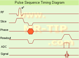
Gradient Echo Sequence Timing Diagram (GRE - sequence) A gradient echo is generated by using a pair of bipolar gradient pulses. In the pulse sequence timing diagram, the basic gradient echo sequence is illustrated. There is no refocusing 180° pulse and the data are sampled during a gradient echo, which is achieved by dephasing the spins with a negatively pulsed gradient before they are rephased by an opposite gradient with opposite polarity to generate the echo.
See also the Pulse Sequence Timing Diagram. There you will find a description of the components.
The excitation pulse is termed the alpha pulse α. It tilts the magnetization by a flip angle α, which is typically between 0° and 90°. With a small flip angle there is a reduction in the value of transverse magnetization that will affect subsequent RF pulses. The flip angle can also be slowly increased during data acquisition (variable flip angle: tilt optimized nonsaturation excitation). The data are not acquired in a steady state, where z-magnetization recovery and destruction by ad-pulses are balanced. However, the z-magnetization is used up by tilting a little more of the remaining z-magnetization into the xy-plane for each acquired imaging line.
Gradient echo imaging is typically accomplished by examining the FID, whereas the read gradient is turned on for localization of the signal in the readout direction. T2* is the characteristic decay time constant associated with the FID. The contrast and signal generated by a gradient echo depend on the size of the longitudinal magnetization and the flip angle. When α = 90° the sequence is identical to the so-called partial saturation or saturation recovery pulse sequence. In standard GRE imaging, this basic pulse sequence is repeated as many times as image lines have to be acquired. Additional gradients or radio frequency pulses are introduced with the aim to spoil to refocus the xy-magnetization at the moment when the spin system is subject to the next α pulse.
As a result of the short repetition time, the z-magnetization cannot fully recover and after a few initial α pulses there is an equilibrium established between z-magnetization recovery and z-magnetization reduction due to the α pulses.
Gradient echoes have a lower SAR, are more sensitive to field inhomogeneities and have a reduced crosstalk, so that a small or no slice gap can be used. In or out of phase imaging depending on the selected TE (and field strength of the magnet) is possible. As the flip angle is decreased, T1 weighting can be maintained by reducing the TR. T2* weighting can be minimized by keeping the TE as short as possible, but pure T2 weighting is not possible. By using a reduced flip angle, some of the magnetization value remains longitudinal (less time needed to achieve full recovery) and for a certain T1 and TR, there exist one flip angle that will give the most signal, known as the "Ernst angle".
Contrast values:
PD weighted: Small flip angle (no T1), long TR (no T1) and short TE (no T2*)
T1 weighted: Large flip angle (70°), short TR (less than 50ms) and short TE
T2* weighted: Small flip angle, some longer TR (100 ms) and long TE (20 ms)

Classification of GRE sequences can be made into four categories:
See also Gradient Recalled Echo Sequence, Spoiled Gradient Echo Sequence, Refocused Gradient Echo Sequence, Ultrafast Gradient Echo Sequence.
 
Images, Movies, Sliders:
 MRI Liver In Phase  Open this link in a new window
    
 MRI Liver Out Of Phase  Open this link in a new window
    
 MVP Parasternal  Open this link in a new window
 Breast MRI Images T1 Pre - Post Contrast  Open this link in a new window
 Circle of Willis, Time of Flight, MIP  Open this link in a new window
    
SlidersSliders Overview

 
spacer

• View the DATABASE results for 'Gradient Echo Sequence' (70).Open this link in a new window

 
Further Reading:
  Basics:
Enhanced Fast GRadient Echo 3-Dimensional (efgre3D) or THRIVE
   by www.mri.tju.edu    
  News & More:
MRI evaluation of fatty liver in day to day practice: Quantitative and qualitative methods
Wednesday, 3 September 2014   by www.sciencedirect.com    
T1rho-prepared balanced gradient echo for rapid 3D T1rho MRI
Monday, 1 September 2008   by www.ncbi.nlm.nih.gov    
Searchterm 'AIN' was also found in the following services: 
spacer
News  (888)  Resources  (128)  Forum  (209)  
 
LiposomesInfoSheet: - Contrast Agents - 
Intro, Overview, 
Characteristics, 
Types of, 
etc.
 
Generic name: Liposomes, central moiety: different, contrast effect: paramagnetic, distribution: different
Liposomes are lipid containing nanoparticles, or fat molecules, surrounding a water core. Liposomes were the first type of nanoparticles created to be used as carriers for lipophilic MRI contrast agents with novel characteristics.
Liposomes loaded with gadolinium-containing chelates have potential as blood pool agents, caused by modifications of the surface (e.g., with polyethylene glycol) leading to longer blood retention times.
The incorporation of contrast agents into either the the bilayer membrane or the aqueous inner cavity is possible. These MRI contrast agents has been used to image the lymph nodes using liposomes containing Gd-DTPA as well as dextran coated iron oxide particles.
To image the liver or the hepatobiliary system, liposomes containing Gd-HPDO3A, or MnDPDP, have been tested.
Liposomes containing gadolinium were conjugated to antibodies and targeted to a specific organ system.
A method of targeting tumors with ultrasound that also uses MRI to watch the cell destroying, uses liposomes loaded with cytotoxic drugs and also with gadolinium to make them show up in MRI. As well as used as an imaging technique, ultrasound can also be used to destroy cancer cells. Once the drugs have been administered, focusing the ultrasound on the target area makes blood vessels permeable. The liposomes leak out of the blood vessel into the target area, watched by MRI, where the cytotoxic drug can then go to work.

See also Memosomes, Superparamagnetic Iron Oxide, Classifications, Characteristics, etc. and Mangafodipir Trisodium.
spacer

• View the DATABASE results for 'Liposomes' (6).Open this link in a new window


• View the NEWS results for 'Liposomes' (1).Open this link in a new window.
 
Further Reading:
  Basics:
Novel Agent for Lymph Node Imaging and Targeted Gene Therapy
1997   by cbcrp.org.127.seekdotnet.com    
DELIVERY AND ACTIVATION OF CONTRAST AGENTS FOR MAGNETIC RESONANCE IMAGING(.pdf)
   by thesis.library.caltech.edu    
New MRI Contrast Agent Under Development
Friday, 16 January 2009   by www.medgadget.com    
New Method Combines MRI, HIFU, Temperature-Sensitive Liposomes for Chemo Delivery Directly to Tumor
Wednesday, 9 February 2011   by www.medgadget.com    
  News & More:
Specialized MRI sensor can detect light deep within tissues
Thursday, 22 December 2022
Multimodal Nanoparticles for Quantitative Imaging(.pdf)
Tuesday, 13 December 2011   by alexandria.tue.nl    
Molecular Magnetic Resonance Imaging(.pdf)
2005   by www.medical.siemens.com    
MRI Resources 
General - Directories - IR - Safety pool - Supplies - Patient Information
 
Magnetization Transfer Contrast
 
(MTC) This MRI method increases the contrast by removing a portion of the total signal in tissue. An off resonance radio frequency (RF) pulse saturates macromolecular protons to make them invisible (caused by their ultra-short T2* relaxation times). The MRI signal from semi-solid tissue like brain parenchyma is reduced, and the signal from a more fluid component like blood is retained.
E.g., saturation of broad spectral lines may produce decreases in intensity of lines not directly saturated, through exchange of magnetization between the corresponding states; more closely coupled states will show a greater resulting intensity change. Magnetization transfer techniques make demyelinated brain or spine lesions (as seen e.g. in multiple sclerosis) better visible on T2 weighted images as well as on gadolinium contrast enhanced T1 weighted images.
Off resonance makes use of a selection gradient during an off resonance MTC pulse. The gradient has a negative offset frequency on the arterial side of the imaging volume (caudally more off resonant and cranially less off resonant). The net effect of this type of pulse is that the arterial blood outside the imaging volume will retain more of its longitudinal magnetization, with more vascular signal when it enters the imaging volume. Off resonance MTC saturates the venous blood, leaving the arterial blood untouched.
On resonance has no effect on the free water pool but will saturate the bound water pool and is the difference in T2 between the pools. Special binomial pulses are transmitted causing the magnetization of the free protons to remain unchanged. The z-magnetization returns to its original value. The spins of the bound pool with a short T2 experience decay, resulting in a destroyed magnetization after the on resonance pulse.

See also Magnetization Transfer.
spacer

• View the DATABASE results for 'Magnetization Transfer Contrast' (5).Open this link in a new window

 
Further Reading:
  News & More:
MRI of the Human Eye Using Magnetization Transfer Contrast Enhancement
   by www.iovs.org    
MRI Resources 
Software - Crystallography - MR Myelography - Implant and Prosthesis pool - Sequences - Stent
 
previous      16 - 20 (of 352)     next
Result Pages : [1 2]  [3 4 5 6 7 8 9 10 11 12 13 14 15 16 17 18 19 20 ... ]
 Random Page
 
Share This Page
FacebookTwitterLinkedIn

MR-TIP    
Community   
User
Pass
Forgot your UserID/Password ?    


Next big thing in MRI will be :
AI 
remote operator 
personalized protocols 
helium-free 
molecular MRI 
portable MRI 

Look
      Ups


MR-TIP.com uses cookies! By browsing MR-TIP.com, you agree to our use of cookies.

Magnetic Resonance - Technology Information Portal
Member of SoftWays' Medical Imaging Group - MR-TIP • Radiology-TIP • Medical-Ultrasound-Imaging • 
Copyright © 2003 - 2024 SoftWays. All rights reserved. [ 18 September 2024]
Terms of Use | Privacy Policy | Advertising
 [last update: 2024-02-26 03:41:00]