| Info
Sheets |
| | | | | | | | | | | | | | | | | | | | | | | | |
 | Out-
side |
| | | | |
|
| | | | | |  | Searchterm 'Bo' was also found in the following services: | | | | |
|  |  |
| |
|
(SAR) The Specific Absorption Rate is defined as the RF power absorbed per unit of mass of an object, and is measured in watts per kilogram (W/kg).
The SAR describes the potential for heating of the patient's tissue due to the application of the RF energy necessary to produce the MR signal. Inhomogeneity of the RF field leads to a local exposure where most of the absorbed energy is applied to one body region rather than the entire person, leading to the concept of a local SAR. Hot spots may occur in the exposed tissue, to avoid or at least minimize effects of such theoretical complications, the frequency and the power of the radio frequency irradiation should be kept at the lowest possible level. Averaging over the whole body leads to the global SAR.
It increases with field strength, radio frequency power and duty cycle, transmitter-coil type and body size. The doubling of the field strength from 1.5 Tesla (1.5T) to 3 Tesla ( 3T) leads to a quadrupling of SAR. In high and ultrahigh fields, some of the multiple echo, multiple-slice pulse sequences may create a higher SAR than recommended by the agencies. SAR can be reduced by lower flip angle and longer repetition times, which could potentially affect image contrast.
Normally no threatening increase in temperature could be shown. Even in high magnetic fields, the local temperature increases not more than 1°C. 2.1°C is the highest measured increase in skin temperature. Eddy currents may heat up implants and thus may cause local heating.
FDA SAR limits:
•
Whole body: 4W/kg/15-minute exposure averaged;
•
Head: 3W/kg/10-minute exposure averaged;
•
Head or torso: 8W/kg/5 minute exposure per gram of tissue;
•
Extremities: 12W/kg/5 minute exposure per gram of tissue.
IEC (International Electrotechnical Commission) SAR limits of some European countries:
All limits are averaged over 6 minutes.
•
Level 0 (normal operating mode): Whole body 2W/kg; Head 3.2W/kg; Head or Torso (local) 10W/kg;
Extremities (local) 20W/kg;
•
Level I (first level controlled operating mode): Whole body 4W/kg; Head 3.2W/kg; Head or Torso (local) 10W/kg; Extremities (local) 20W/kg;
•
Level II (second level controlled operating mode): All values are over Level I values.
(For more details: IEC 60601-2-33 (2002))
In most countries standard MRI systems are limited to a maximum SAR of 4 W/kg, so most scanning in level II is impossible.
For Level I, in addition to routine monitoring, particular caution must be exercised for patients who are sensitive to temperature increases or to RF energy.
For Japan different SAR limits are valid. | | | | | | | | | | |  Further Reading: Further Reading: | | Basics:
|
|
News & More:
| |
| |
| | | | | |
| |
|
In simple ultrafast GRE imaging, TR and TE are so short, that tissues have a poor imaging signal and - more importantly - poor contrast except when contrast media enhanced ( contrast enhanced angiography). Therefore, the magnetization is 'prepared' during the preparation module, most frequently by an initial 180° inversion pulse.
In the pulse sequence timing diagram, the basic ultrafast gradient echo sequence is illustrated. The 180° inversion pulse is executed one time (to the left of the vertical line), the right side represents the data collection period and is often repeated depending on the acquisition parameters.
See also Pulse Sequence Timing Diagram, there you will find a description of the components.
Ultrafast GRE sequences have a short TR,TE, a low flip angle and TR is so short that image acquisition lasts less than 1 second and typically less than 500 ms. Common TR: 3-5 msec, TE: 2 msec, and the flip angle is a bout 5°.
Such sequences are often labeled with the prefix 'Tur bo' like TurboFLASH, Tur boFFE and Tur boGRASS.
This allows one to center the subsequent ultrafast GRE data acquisition around the inversion time TI, where one of the tissues of interest has very little signal as its z-magnetization is passing through zero.
Unlike a standard inversion recovery (IR) sequence, all lines or a substantial segment of k-space image lines are acquired after a single inversion pulse, which can then together be considered as readout module. The readout module may use a variable flip angle approach, or the data acquisition may be divided into multiple segments (shots). The latter is useful particularly in cardiac imaging where acquiring all lines in a single segment may take too long relative to the cardiac cycle to provide adequate temporal resolution.
If multiple lines are acquired after a single pulse, the pulse sequence is a type of gradient echo echo planar imaging (EPI) pulse sequence. See also Magnetization Prepared Rapid Gradient Echo ( MPRAGE) and Turbo Field Echo ( TFE). | | | |
• View the DATABASE results for 'Ultrafast Gradient Echo Sequence' (13).
| | | | |
| | | | | |
| |
|
(CE MRA) Contrast enhanced MR angiography is based on the T1 values of blood, the surrounding tissue, and paramagnetic contrast agent.
T1-shortening contrast agents reduces the T1 value of the blood (approximately to 50 msec, shorter than that of the surrounding tissues) and allow the visualization of blood vessels, as the images are no longer dependent primarily on the inflow effect of the blood.
Contrast enhanced MRA is performed with a short TR to have low signal (due to the longer T1) from the stationary tissue, short scan time to facilitate breath hold imaging, short TE to minimize T2* effects and a bolus injection of a sufficient dose of a gadolinium chelate.
Images of the region of interest are performed with 3D spoiled gradient echo pulse sequences. The enhancement is maximized by timing the contrast agent injection such that the period of maximum arterial concentration corresponds to the k-space acquisition. Different techniques are used to ensure optimal contrast of the arteries e.g., bolus timing, automatic bolus detection, bolus tracking, care bolus.
A high resolution with near isotropic voxels and minimal pulsatility and misregistration artifacts should be striven for. The postprocessing with the maximum intensity projection ( MIP) enables different views of the 3D data set.
Unlike conventional MRA techniques based on velocity dependent inflow or phase shift techniques, contrast enhanced MRA exploits the
gadolinium induced T1-shortening effects. CE MRA reduces or eliminates most of the artifacts of time of flight angiography or phase contrast angiography. Advantages are the possibility of in plane imaging of the blood vessels, which allows to examine large parts in a short time and high resolution scans in one breath hold.
CE MRA has found a wide acceptance in the clinical routine, caused by the
advantages:
•
3D MRA can be acquired in any plane, which means that
greater vessel coverage can be obtained at high
resolution with fewer slices (aorta, peripheral vessels);
•
the possibility to perform a time resolved examination
(similarly to conventional angiography);
•
no use of ionizing radiation; paramagnetic agents have a beneficial safety.
| | | | | |
• View the DATABASE results for 'Contrast Enhanced Magnetic Resonance Angiography' (14).
| | |
• View the NEWS results for 'Contrast Enhanced Magnetic Resonance Angiography' (2).
| | | | | | Further Reading: | Basics:
|
|
News & More:
| |
| |
| | | Searchterm 'Bo' was also found in the following services: | | | | |
| | |
| |
|
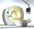
'MRI system is not an expensive equipment anymore.
ENCORE developed by ISOL Technology is a low cost MRI system with the advantages like of the 1.0T MRI scanner. Developed specially for the overseas market, the ENCORE is gaining popularity in the domestic market by medium sized hospitals.
Due to the optimum RF and Gradient application technology. ENCORE enables to obtain high resolution imaging and 2D/3D Angio images which was only possible in high field MR systems.'
- Less consumption of the helium gas due to the ultra-lightweight magnet specially designed and manufactured for ISOL.
- Cost efficiency MR system due to air cooling type (equivalent to permanent magnetic).
- Patient processing speed of less than 20 minutes.'
Device Information and Specification
CLINICAL APPLICATION
Whole body
CONFIGURATION
Short bore compact
| | | |
• View the DATABASE results for 'ENCORE 0.5T™' (2).
| | | | |
| | | | | |
| |
|
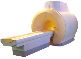
Device Information and Specification
CLINICAL APPLICATION
Whole body
CONFIGURATION
Short bore compact
Standard: head, body, C1, C3; Optional: Small joint, flex-E, flex-R, endocavitary (L and S), dual TMJ, knee, neck, T/L spine, breast; Optional phased array: Spine, pediatric, 3rd party connector, Flex-S-M-L, flex body, flex cardiac, neuro-vascular, head
SE, Modified-SE ( TSE), DAVE, STIR, FLAIR, SPIR, MTC, Dynamic, Keyhole, CLEAR, Q Flow, Balanced FFE, Multi Chunk 3D, Multi Stack 3D, FFE-EPI, SE-EPI, IR-EPI, GRASE, Diffusion Imaging, Perfusion Imaging;; Angiography: Inflow MRA, TONE, PCA, CE MRA
RapidView Recon. greater than 500 @ 256 Matrix
128 x 128, 256 x 256,512 x 512,1024 x 1024
Variable in 1% increments
Lum.: 120 cd/m2; contrast: 150:1
Variable (op. param. depend.)
POWER REQUIREMENTS
380/400 V
| | | |
• View the DATABASE results for 'Intera 0.5T™' (2).
| | | | |
| | | | |
| | | |
|
| |
 | Look
Ups |
| |