| Info
Sheets |
| | | | | | | | | | | | | | | | | | | | | | | | |
 | Out-
side |
| | | | |
|
| | | | | |  | Searchterm 'Bo' was also found in the following services: | | | | |
|  |  |
| |
|
Time-dependent electromagnetic fields are significantly attenuated by conducting media (including the human body); the skin depth gives a measure of the average depth of penetration of the RF field.
A high power frequency tunable RF source can be rapidly switched on and off. This produces a large RF field perpendicular to the magnetic field. This RF field is focused by the body coil. The RF source and coils must be tunable in both frequency and impedance to
'match the impedance' of the patient's body.
The skin depth may be a limiting factor in MR imaging at very high frequencies (high magnetic fields). The skin depth also affects the Q of the coils. | | | | | |  Further Reading: Further Reading: | News & More:
|
|
| |
| | | | | |
| |
|
A surface coil is essentially a loop of conducting material, such as copper tubing. The in- bore solenoidal sending coil is used as the transmitter of RF energy. This type of receiver coil is placed directly on or over the region of interest for increased magnetic sensitivity. The loop may form various shapes and be bent slightly to conform to the imaged body part. Surface coils have a good SNR for tissues adjacent to the coil and because the signal decrease with the distance, an eligibility homogeneity correction will equalize this over the field of view. A rule of thumb for surface coils is that the sensitivity decreases appreciably beyond a distance equal to the diameter of the coil.
The positioning of the coil is an important determinant of performance. As only the region close to the surface coil will contribute to the signal, there is an improvement in the SNR for these regions, compared to the use of receiver coils that surround the appropriate part of the body. These coils are specifically designed for localized body regions, and provide improved signal to noise ratios by limiting the spatial extent of the excitation or reception.
See also the related poll result: ' 3rd party coils are better than the original manufacturer coils' | | | |
• View the DATABASE results for 'Surface Coil' (81).
| | | | | | Further Reading: | Basics:
|
|
| |
| | | | | |
| |
|
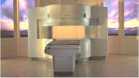
From Hitachi Medical Systems America Inc.;
the AIRIS II, an entry in the diagnostic category of open MR systems, was designed by Hitachi
Medical Systems America Inc. (Twinsburg, OH, USA) and Hitachi Medical Corp. (Tokyo) and is manufactured by the Tokyo branch. A 0.3 T field-strength magnet and phased array coils deliver high image quality without the need for a tunnel-type high-field system, thereby significantly improving patient comfort not only for claustrophobic patients.
Device Information and Specification
CLINICAL APPLICATION
Whole body
QD Head, MA Head and Neck, QD C-Spine, MA or QD Shoulder, MA CTL Spine, QD Knee, Neck, QD TMJ, QD Breast, QD Flex Body (4 sizes), Small and Large Extrem., QD Wrist, MA Foot and Ankle (WIP), PVA (WIP)
SE, GE, GR, IR, FIR, STIR, FSE, ss-FSE, FLAIR, EPI -DWI, SE-EPI, ms - EPI, SSP, MTC, SARGE, RSSG, TRSG, MRCP, Angiography: CE, 2D/3D TOF
IMAGING MODES
Single, multislice, volume study
TR
SE: 30 - 10,000msec GE: 20 - 10,000msec IR: 50 - 16,700msec FSE: 200 - 16,7000msec
TE
SE : 10 - 250msec IR: 10 -250msec GE: 5 - 50 msec FSE: 15 - 2,000
0.05 sec/image (256 x 256)
2D: 2 - 100 mm; 3D: 0.5 - 5 mm
Level Range: -2,000 to +4,000
POWER REQUIREMENTS
208/220/240 V, single phase
COOLING SYSTEM TYPE
Air-cooled
2.0 m lateral, 2.5 m vert./long
| | | |
• View the DATABASE results for 'AIRIS II™' (2).
| | | | |
| | | Searchterm 'Bo' was also found in the following services: | | | | |
| | |
| |
|
| | | | | | | Further Reading: | News & More:
|
|
| |
| | | | | |
| |
|

FDA cleared and CE Mark 2011.
The Biograph mMR has a fully-integrated design for simultaneous PET/MRI imaging. The dedicated hardware includes solid-state, avalanche photodiode PET detector and adapted, PET-compatible MR coils.
The possibility of truly simultaneous operation allows the acquisition of several magnetic resonance imaging ( MRI) sequences during the positron emission tomography (PET) scan, without increasing the examination time.
See also Hybrid Imaging.
Device Information and Specification
CLINICAL APPLICATION
Whole Body
CONFIGURATION
Simultaneous PET/MRI
26 cm (typical overlap 23%)
A-P 45, R-L 50, H-F 50 cm
PET RING DIAMETER
65.6 cm
PATIENT SCAN RANGE
199 cm
HORIZONTAL SPEED
200 mmsec
PET DETECTOR
Solid state, 4032 avalanche photo diodes
DETECTOR SCINTILLATION MATERIAL
LSO, 28672 crystals
CRYSTAL SIZE
4 x 4 x 20 mm
DIMENSION H*W*D (gantry included)
335 x 230 x 242 cm (finshed covers)
COOLING SYSTEM
PET system: water; MRI system: water
Aautomatic, patient specific shim; active shim 3 linear and 5 non-linear channels (seond order)
POWER REQUIREMENTS
380 / 400 / 420 / 440 / 460 / 480 V, 3-phase + ground; Total system 110kW
| | | | | | | Further Reading: | | Basics:
|
|
News & More:
| |
| |
| | | | |
| | | |
|
| |
 | Look
Ups |
| |