Magnetic Resonance - Technology Information Portal Welcome to MRI Technology
Info
  Sheets

Out-
      side


 'Digital' 
SEARCH FOR    
 
  2 3 5 A B C D E F G H I J K L M N O P Q R S T U V W X Y Z
Result : Searchterm 'Digital' found in 3 terms [] and 25 definitions []
previous     21 - 25 (of 28)     next
Result Pages : [1]  [2 3 4 5 6]
Searchterm 'Digital' was also found in the following services: 
spacer
News  (20)  Resources  (14)  Forum  (1)  
 
Phased Array CoilInfoSheet: - Coils - 
Intro, 
Overview, 
etc.MRI Resource Directory:
 - Coils -
 
The phased array coils operate typically as receive only coils. In that case, the in the MRI device implemented body coil act as the transmitter and sends the radio frequency energy to generate the excitation pulses. State-of-the-art array coil systems include the use of 4 (up to 32) coils with separate receivers. This method is often referred to as a phased array system, although the signals are not added such that the signal phase information is included. The use of phased array coils allows the decreasing of the number of signal averages, which shortens the scan time by high SNR and resolution.
High-sensitivity RF surface coils and digital processing algorithms have been developed that speed up image acquisition and reconstruction during the MRI scan.
Fast parallel imaging techniques, for example sensitivity encoding (SENSE), 'Partially Parallel Imaging with Localized Sensitivity' (PILS), Simultaneous Acquisition of Spatial Harmonics (SMASH) or Array Spatial Sensitivity Encoding Technique (ASSET) use phased array multichannel coils to further improve spatial and temporal resolution. The sensitivity profile of a phased array coil element is measured by a separate low resolution 3D acquisition over the entire field of view in the case of a SENSE acquisition. For an mSENSE measurement, a self-calibration acquires some of the missing lines in the center of the k-space.
Also called linear array coil or synergy surface coil.

See also the related poll result: '3rd party coils are better than the original manufacturer coils'
spacer
 
• Related Searches:
    • Coil Diameter
    • Switchable Coil
    • Sensitive Volume
    • Radio Frequency Coil
    • Parallel Imaging Technique
 
Further Reading:
  Basics:
Coil Arrays for Parallel MRI: Introduction and Overview.
   by www.mr.ethz.ch    
MRI Resources 
Absorption and Emission - Journals - Jobs pool - Software - Calculation - NMR
 
Pulse Sequence Timing DiagramInfoSheet: - Sequences - 
Intro, 
Overview, 
Types of, 
etc.
 
Spin Echo Timing Diagram The schematic figures of a pulse sequence timing diagram illustrate the steps of basic hardware activity that are incorporated into a pulse sequence. Time during sequence execution is indicated along the horizontal axes. Each line belongs to a different hardware component. One line is needed for the radio frequency transmitter and also one for each gradient (Gs = slice selection gradient x, Gf = phase encoding gradient y, Gf = frequency encoding gradient z, also called readout gradient).
In picture 1, a timing diagram for a 2D pulse sequence is shown.
Slice selection and signal detection are repeated in duration, relative timing and amplitude, each time the sequence is repeated. A single phase encoding component is present each time the sequence is executed.
Additional lines are added for ADC (Analog to Digital Converter) and sampling. A gradient pulse is shown as a deviation above or below the horizontal line. Simultaneous component activities such as the RF pulse and slice selection gradient are indicated as a non-zero deviation from both lines at the same horizontal position. Simple deviations from zero show constant amplitude gradient pulse. Gradient amplitudes that change during the measurement, e.g. phase encoding are represented as hatched regions.

Spin Echo Timing Diagram The second picture shows a timing diagram for a 3D pulse sequence.
Volume excitation and signal detection are repeated in duration, relative timing and amplitude, each time the sequence is repeated. Two phase encoding components are present, one in the phase encoding direction and the other in slice selection direction (irrespectively incremented in amplitude) in each time the sequence is executed. A description of the comparison of hardware activity between different pulse sequences.
spacer

• View the DATABASE results for 'Pulse Sequence Timing Diagram' (7).Open this link in a new window

MRI Resources 
Online Books - Diffusion Weighted Imaging - MRI Technician and Technologist Schools - Jobs - Open Directory Project - Education pool
 
Quadrature Detector
 
The quadrature detector is a part of the receiver that converts the high-frequency MRI signal to a lower frequency. This phase sensitive detector or demodulator detects the components of the signal in phase with a reference signal and 90° out of phase with the reference signal. The modulated signal contains i.e. the frequency range across the field of view encoded by the frequency encoding gradient. This may be performed by either analog or digital means.
spacer

• View the DATABASE results for 'Quadrature Detector' (7).Open this link in a new window

Searchterm 'Digital' was also found in the following services: 
spacer
News  (20)  Resources  (14)  Forum  (1)  
 
RELAX 0.35T™InfoSheet: - Devices -
Intro, 
Types of Magnets, 
Overview, 
etc.MRI Resource Directory:
 - Devices -
 
www.isoltech.co.kr/english/product/035t.htm 
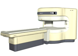
From ISOL Technology
'RELAX is open type MRI system created by making up for the weakness of existing conventional MR systems and applying the strength and the application of the middle to high field MR without uncompromising the image quality.
RELAX offers you a premium mix of form, performance and functionality that are patient and user friendly beyond comparison. - New breed of MRI pursuing - patients comfort'
Device Information and Specification
CLINICAL APPLICATION
Whole body
CONFIGURATION
Open
Head, C-spine, L-spine, TMJ, Knee, Shoulder, General purpose, Phased Array System: 4 digital receiver channels (Up to 12 channels)
SYNCHRONIZATION
ECG/peripheral: Optional/yes, respiratory gating
PULSE SEQUENCES
2D/3D Spin echo, 2D/3D Gradient echo, 2D/3D Fast spin echo, Inversion recovery, 2D/3D Fast gradient echo sequences, FLAIR/STIR, 2D/3D TOF
IMAGING MODES
3D volume imaging (MIP, MPR) MR Angiography package
30 cm
MAGNET TYPE
Permanent
40 cm diameter (patient)
MAGNET WEIGHT
13500 kg
H*W*D
170 x 210 x 130 cm
COOLING SYSTEM TYPE
Water-cooled coil and air-cooled amplifier
STRENGTH
25 - 30 mT/m
5-GAUSS FRINGE FIELD
lower than 2.4 m from the iso-center
Passive and active
spacer

• View the DATABASE results for 'RELAX 0.35T™' (2).Open this link in a new window

MRI Resources 
Breast MRI - Brain MRI - General - NMR - Lung Imaging - MRI Centers
 
Radio Frequency Overflow ArtifactInfoSheet: - Artifacts - 
Case Studies, 
Reduction Index, 
etc.MRI Resource Directory:
 - Artifacts -
 
Quick Overview
Please note that there are different common names for this artifact.
Artifact Information
NAME
Radio frequency overflow, data clipping
DESCRIPTION
Image non-uniform
REASON
Signal too intense
HELP
Manually decrease of the receiver gain
The received radio frequency signal is too strong, parts of the signal get lost by converting from analog to digital, resulting in a washed out image.
mri safety guidance
Image Guidance
Auto-prescanning usually adjusts the amplification at the receiver in a way, that the received signal could be processed without any loss. Else the receiver gain must be corrected manually.

See also Data Clipping Artifact, Artifact Overview and Artifacts Reduction Index.
spacer

• View the DATABASE results for 'Radio Frequency Overflow Artifact' (2).Open this link in a new window

 
Further Reading:
  Basics:
RF Overflow Artifacts
   by www.mritutor.org    
  News & More:
Magnetic Resonance Imaging (MRI)
2003   by www.hull.ac.uk    
MRI Resources 
MR Guided Interventions - Pregnancy - Education - Services and Supplies - Implant and Prosthesis - Pediatric and Fetal MRI
 
previous      21 - 25 (of 28)     next
Result Pages : [1]  [2 3 4 5 6]
 Random Page
 
Share This Page
FacebookTwitterLinkedIn

MR-TIP    
Community   
User
Pass
Forgot your UserID/Password ?    


Personalized protocols (age, gender, body habitus, etc.) lead to :
more automated planning 
improved patient comfort 
better diagnostics 
optimized image quality 
nothing 

Look
      Ups


MR-TIP.com uses cookies! By browsing MR-TIP.com, you agree to our use of cookies.

Magnetic Resonance - Technology Information Portal
Member of SoftWays' Medical Imaging Group - MR-TIP • Radiology-TIP • Medical-Ultrasound-Imaging • 
Copyright © 2003 - 2024 SoftWays. All rights reserved. [ 23 June 2024]
Terms of Use | Privacy Policy | Advertising
 [last update: 2024-02-26 03:41:00]