Magnetic Resonance - Technology Information Portal Welcome to MRI Technology
Info
  Sheets

Out-
      side


 'Imaging' 
SEARCH FOR    
 
  2 3 5 A B C D E F G H I J K L M N O P Q R S T U V W X Y Z
Result : Searchterm 'Imaging' found in 72 terms [] and 403 definitions []
previous     96 - 100 (of 475)     next
Result Pages : [1 2 3 4 5 6 7 8 9 10 11 12 13 14 15]  [16 17 18 19 20 ... ]
Searchterm 'Imaging' was also found in the following services: 
spacer
News  (1520)  Resources  (268)  Forum  (88)  
 
DeviceForum -
related threadsInfoSheet: - Devices -
Intro, 
Types of Magnets, 
Overview, 
etc.
 
Magnetic resonance imaging (MRI) is based on the magnetic resonance phenomenon, and is used for medical diagnostic imaging since ca. 1977 (see also MRI History).
The first developed MRI devices were constructed as long narrow tunnels. In the meantime the magnets became shorter and wider. In addition to this short bore magnet design, open MRI machines were created. MRI machines with open design have commonly either horizontal or vertical opposite installed magnets and obtain more space and air around the patient during the MRI test.
The basic hardware components of all MRI systems are the magnet, producing a stable and very intense magnetic field, the gradient coils, creating a variable field and radio frequency (RF) coils which are used to transmit energy and to encode spatial positioning. A computer controls the MRI scanning operation and processes the information.
The range of used field strengths for medical imaging is from 0.15 to 3 T. The open MRI magnets have usually field strength in the range 0.2 Tesla to 0.35 Tesla. The higher field MRI devices are commonly solenoid with short bore superconducting magnets, which provide homogeneous fields of high stability.
There are this different types of magnets:
The majority of superconductive magnets are based on niobium-titanium (NbTi) alloys, which are very reliable and require extremely uniform fields and extreme stability over time, but require a liquid helium cryogenic system to keep the conductors at approximately 4.2 Kelvin (-268.8° Celsius). To maintain this temperature the magnet is enclosed and cooled by a cryogen containing liquid helium (sometimes also nitrogen).
The gradient coils are required to produce a linear variation in field along one direction, and to have high efficiency, low inductance and low resistance, in order to minimize the current requirements and heat deposition. A Maxwell coil usually produces linear variation in field along the z-axis; in the other two axes it is best done using a saddle coil, such as the Golay coil.
The radio frequency coils used to excite the nuclei fall into two main categories; surface coils and volume coils. The essential element for spatial encoding, the gradient coil sub-system of the MRI scanner is responsible for the encoding of specialized contrast such as flow information, diffusion information, and modulation of magnetization for spatial tagging.
An analog to digital converter turns the nuclear magnetic resonance signal to a digital signal. The digital signal is then sent to an image processor for Fourier transformation and the image of the MRI scan is displayed on a monitor.

For Ultrasound Imaging (USI) see Ultrasound Machine at Medical-Ultrasound-Imaging.com.

See also the related poll results: 'In 2010 your scanner will probably work with a field strength of' and 'Most outages of your scanning system are caused by failure of'
Radiology-tip.comradGamma Camera,  Linear Accelerator
spacer
Medical-Ultrasound-Imaging.comUltrasound Machine,  Real-Time Scanner
spacer
 
• Related Searches:
    • Superconducting Magnet
    • Class I, II, III Devices
    • Magnet
    • Fringe Field
    • Permanent Magnet
 
Further Reading:
  News & More:
small-steps-can-yield-big-energy-savings-and-cut-emissions-mris
Thursday, 27 April 2023   by www.itnonline.com    
Portable MRI can detect brain abnormalities at bedside
Tuesday, 8 September 2020   by news.yale.edu    
Point-of-Care MRI Secures FDA 510(k) Clearance
Thursday, 30 April 2020   by www.diagnosticimaging.com    
World's First Portable MRI Cleared by FDA
Monday, 17 February 2020   by www.medgadget.com    
Low Power MRI Helps Image Lungs, Brings Costs Down
Thursday, 10 October 2019   by www.medgadget.com    
Cheap, portable scanners could transform brain imaging. But how will scientists deliver the data?
Tuesday, 16 April 2019   by www.sciencemag.org    
The world's strongest MRI machines are pushing human imaging to new limits
Wednesday, 31 October 2018   by www.nature.com    
Kyoto University and Canon reduce cost of MRI scanner to one tenth
Monday, 11 January 2016   by www.electronicsweekly.com    
A transportable MRI machine to speed up the diagnosis and treatment of stroke patients
Wednesday, 22 April 2015   by medicalxpress.com    
Portable 'battlefield MRI' comes out of the lab
Thursday, 30 April 2015   by physicsworld.com    
Chemists develop MRI technique for peeking inside battery-like devices
Friday, 1 August 2014   by www.eurekalert.org    
New devices doubles down to detect and map brain signals
Monday, 23 July 2012   by scienceblog.com    
MRI Resources 
Shoulder MRI - DICOM - Movies - General - MRI Physics - Knee MRI
 
Fast Relaxation Fast Spin EchoInfoSheet: - Sequences - 
Intro, 
Overview, 
Types of, 
etc.
 
(FRFSE, FR-FSE) The fast relaxation fast spin echo sequence provides high signal intensity of fluids even with short repetition times, and can be used with parallel imaging techniques for short breath hold imaging or respiratory gating for free-breathing, high isotropic resolution MR imaging. After signal decay at the end of the echo train, a negative 90° pulse align spins with long T2 from the transverse plane to the longitudinal plane, leading to a much faster recovery of tissues with long T2 time to the equilibrium and thus better contrast between tissues with long and short T2.
Fast relaxation FSE has advantages also for volumetric imaging as the TR can be substantially reduced and thus the scan time. The sequence can be post processed with maximum intensity projection, surface or volume rendering algorithms to visualize anatomical details in brain or spine MRI. Cerebro spinal fluid pulsation artifacts, often problematic in the cervical or thoracic spine may be reduced by radial sampling, in particular when combined with acquisitions of the PROPELLER type.

See also Fast spin echo, Driven Equilibrium.
 
Images, Movies, Sliders:
 Shoulder Sagittal T2 FatSat FRFSE  Open this link in a new window
    

Courtesy of  Robert R. Edelman
 Shoulder Axial T2 FatSat FRFSE  Open this link in a new window
 Shoulder Coronal T2 FatSat FRFSE  Open this link in a new window
    

Courtesy of  Robert R. Edelman
 
spacer
MRI Resources 
Services and Supplies - Chemistry - Quality Advice - Shoulder MRI - MRI Centers - NMR
 
Fast Spin EchoForum -
related threadsInfoSheet: - Sequences - 
Intro, 
Overview, 
Types of, 
etc.
 
Fast Spin Echo Diagram (FSE) In the pulse sequence timing diagram, a fast spin echo sequence with an echo train length of 3 is illustrated. This sequence is characterized by a series of rapidly applied 180° rephasing pulses and multiple echoes, changing the phase encoding gradient for each echo.
The echo time TE may vary from echo to echo in the echo train. The echoes in the center of the K-space (in the case of linear k-space acquisition) mainly produce the type of image contrast, whereas the periphery of K-space determines the spatial resolution. For example, in the middle of K-space the late echoes of T2 weighted images are encoded. T1 or PD contrast is produced from the early echoes.
The benefit of this technique is that the scan duration with, e.g. a turbo spin echo turbo factor / echo train length of 9, is one ninth of the time. In T1 weighted and proton density weighted sequences, there is a limit to how large the ETL can be (e.g. a usual ETL for T1 weighted images is between 3 and 7). The use of large echo train lengths with short TE results in blurring and loss of contrast. For this reason, T2 weighted imaging profits most from this technique.
In T2 weighted FSE images, both water and fat are hyperintense. This is because the succession of 180° RF pulses reduces the spin spin interactions in fat and increases its T2 decay time. Fast spin echo (FSE) sequences have replaced conventional T2 weighted spin echo sequences for most clinical applications. Fast spin echo allows reduced acquisition times and enables T2 weighted breath hold imaging, e.g. for applications in the upper abdomen.
In case of the acquisition of 2 echoes this type of a sequence is named double fast spin echo / dual echo sequence, the first echo is usually density and the second echo is T2 weighted image. Fast spin echo images are more T2 weighted, which makes it difficult to obtain true proton density weighted images. For dual echo imaging with density weighting, the TR should be kept between 2000 - 2400 msec with a short ETL (e.g., 4).
Other terms for this technique are:
Turbo Spin Echo
Rapid Imaging Spin Echo,
Rapid Spin Echo,
Rapid Acquisition Spin Echo,
Rapid Acquisition with Refocused Echoes
 
Images, Movies, Sliders:
 Lumbar Spine T2 FSE Sagittal  Open this link in a new window
    

Courtesy of  Robert R. Edelman
 MRI - Anatomic Imaging of the Foot  Open this link in a new window
    
SlidersSliders Overview

 Lumbar Spine T2 FSE Axial  Open this link in a new window
    

Courtesy of  Robert R. Edelman
 
spacer

• View the DATABASE results for 'Fast Spin Echo' (31).Open this link in a new window

 
Further Reading:
  Basics:
MYELIN-SELECTIVE MRI: PULSE SEQUENCE DESIGN AND OPTIMIZATION
   by www.imaging.robarts.ca    
Advances in Magnetic Resonance Neuroimaging
Friday, 27 February 2009   by www.ncbi.nlm.nih.gov    
  News & More:
New MR sequence helps radiologists more accurately evaluate abnormalities of the uterus and ovaries
Thursday, 23 April 2009   by www.eurekalert.org    
Spin echoes, CPMG and T2 relaxation - Introductory NMR & MRI from Magritek
2013   by www.azom.com    
Searchterm 'Imaging' was also found in the following services: 
spacer
News  (1520)  Resources  (268)  Forum  (88)  
 
Generalized Autocalibrating Partially Parallel AcquisitionInfoSheet: - Sequences - 
Intro, 
Overview, 
Types of, 
etc.
 
(GRAPPA) GRAPPA is a parallel imaging technique to speed up MRI pulse sequences. The Fourier plane of the image is reconstructed from the frequency signals of each coil (reconstruction in the frequency domain).
Parallel imaging techniques like GRAPPA, auto-SMASH and VD-AUTO-SMASH are second and third generation algorithms using k-space undersampling. A model from a part of the center of k-space is acquired, to find the coefficients of the signals from each coil element, and to reconstruct the missing intermediary lines. The acquisition of these additional lines is a form of self-calibration, which lengthens the overall short scan time. The acquisition of these k-space lines provides mapping of the whole field as well as data for the image contrast.
Algorithms of the GRAPPA type work better than the SENSE type in heterogeneous body parts like thoracic or abdominal imaging, or in pulse sequences like echo planar imaging. This is caused by differences between the sensitivity map and the pulse sequence (e.g. artifacts) or an unreliable sensitivity map.
spacer

• View the DATABASE results for 'Generalized Autocalibrating Partially Parallel Acquisition' (2).Open this link in a new window

MRI Resources 
Collections - Pacemaker - MR Guided Interventions - Safety pool - Safety Products - Corporations
 
Gradient Echo SequenceForum -
related threadsInfoSheet: - Sequences - 
Intro, 
Overview, 
Types of, 
etc.
 
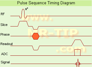
Gradient Echo Sequence Timing Diagram (GRE - sequence) A gradient echo is generated by using a pair of bipolar gradient pulses. In the pulse sequence timing diagram, the basic gradient echo sequence is illustrated. There is no refocusing 180° pulse and the data are sampled during a gradient echo, which is achieved by dephasing the spins with a negatively pulsed gradient before they are rephased by an opposite gradient with opposite polarity to generate the echo.
See also the Pulse Sequence Timing Diagram. There you will find a description of the components.
The excitation pulse is termed the alpha pulse α. It tilts the magnetization by a flip angle α, which is typically between 0° and 90°. With a small flip angle there is a reduction in the value of transverse magnetization that will affect subsequent RF pulses. The flip angle can also be slowly increased during data acquisition (variable flip angle: tilt optimized nonsaturation excitation). The data are not acquired in a steady state, where z-magnetization recovery and destruction by ad-pulses are balanced. However, the z-magnetization is used up by tilting a little more of the remaining z-magnetization into the xy-plane for each acquired imaging line.
Gradient echo imaging is typically accomplished by examining the FID, whereas the read gradient is turned on for localization of the signal in the readout direction. T2* is the characteristic decay time constant associated with the FID. The contrast and signal generated by a gradient echo depend on the size of the longitudinal magnetization and the flip angle. When α = 90° the sequence is identical to the so-called partial saturation or saturation recovery pulse sequence. In standard GRE imaging, this basic pulse sequence is repeated as many times as image lines have to be acquired. Additional gradients or radio frequency pulses are introduced with the aim to spoil to refocus the xy-magnetization at the moment when the spin system is subject to the next α pulse.
As a result of the short repetition time, the z-magnetization cannot fully recover and after a few initial α pulses there is an equilibrium established between z-magnetization recovery and z-magnetization reduction due to the α pulses.
Gradient echoes have a lower SAR, are more sensitive to field inhomogeneities and have a reduced crosstalk, so that a small or no slice gap can be used. In or out of phase imaging depending on the selected TE (and field strength of the magnet) is possible. As the flip angle is decreased, T1 weighting can be maintained by reducing the TR. T2* weighting can be minimized by keeping the TE as short as possible, but pure T2 weighting is not possible. By using a reduced flip angle, some of the magnetization value remains longitudinal (less time needed to achieve full recovery) and for a certain T1 and TR, there exist one flip angle that will give the most signal, known as the "Ernst angle".
Contrast values:
PD weighted: Small flip angle (no T1), long TR (no T1) and short TE (no T2*)
T1 weighted: Large flip angle (70°), short TR (less than 50ms) and short TE
T2* weighted: Small flip angle, some longer TR (100 ms) and long TE (20 ms)

Classification of GRE sequences can be made into four categories:
See also Gradient Recalled Echo Sequence, Spoiled Gradient Echo Sequence, Refocused Gradient Echo Sequence, Ultrafast Gradient Echo Sequence.
 
Images, Movies, Sliders:
 MRI Liver In Phase  Open this link in a new window
    
 MRI Liver Out Of Phase  Open this link in a new window
    
 MVP Parasternal  Open this link in a new window
 Breast MRI Images T1 Pre - Post Contrast  Open this link in a new window
 Circle of Willis, Time of Flight, MIP  Open this link in a new window
    
SlidersSliders Overview

 
spacer

• View the DATABASE results for 'Gradient Echo Sequence' (70).Open this link in a new window

 
Further Reading:
  Basics:
Enhanced Fast GRadient Echo 3-Dimensional (efgre3D) or THRIVE
   by www.mri.tju.edu    
  News & More:
MRI evaluation of fatty liver in day to day practice: Quantitative and qualitative methods
Wednesday, 3 September 2014   by www.sciencedirect.com    
T1rho-prepared balanced gradient echo for rapid 3D T1rho MRI
Monday, 1 September 2008   by www.ncbi.nlm.nih.gov    
MRI Resources 
Quality Advice - Libraries - Spine MRI - MRI Reimbursement - Universities - Collections
 
previous      96 - 100 (of 475)     next
Result Pages : [1 2 3 4 5 6 7 8 9 10 11 12 13 14 15]  [16 17 18 19 20 ... ]
 Random Page
 
Share This Page
FacebookTwitterLinkedIn

MR-TIP    
Community   
User
Pass
Forgot your UserID/Password ?    


MRI is trending to low field magnets :
reduced costs will lead to this change 
AI will close the gap to high field 
only in remote areas 
is only temporary 
never 

Look
      Ups


MR-TIP.com uses cookies! By browsing MR-TIP.com, you agree to our use of cookies.

Magnetic Resonance - Technology Information Portal
Member of SoftWays' Medical Imaging Group - MR-TIP • Radiology-TIP • Medical-Ultrasound-Imaging • 
Copyright © 2003 - 2024 SoftWays. All rights reserved. [ 4 December 2024]
Terms of Use | Privacy Policy | Advertising
 [last update: 2024-02-26 03:41:00]