 | Info
Sheets |
| | | | | | | | | | | | | | | | | | | | | | | | |
 | Out-
side |
| | | | |
|
| | | | |
Result : Searchterm 'Slice Profile' found in 1 term [ ] and 5 definitions [ ] and 5 definitions [ ], (+ 3 Boolean[ ], (+ 3 Boolean[ ] results ] results
| previous 6 - 9 (of 9) Result Pages :  [1] [1]  [2] [2] |  | |  | Searchterm 'Slice Profile' was also found in the following service: | | | | |
|  |  |
| |
|
(FWHM) A commonly used measure of the width at half the maximum value of peaked functions such as spectral lines or slice profiles and important measure of the quality of an imaging device and its spatial resolution.
As the name states, the FWHM is measured by identifying the points on the signal curve, which are half the maximum value. The horizontal distance between these two points is called the FWHM. For a spectral line, this will be proportional to 1/T2. | |  | | | |  Further Reading: Further Reading: | | Basics:
|
|
News & More:
| |
| |
|  | |  |  |  |
| |
|

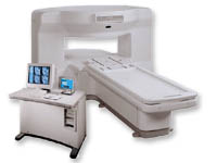
From GE Healthcare;
the New Signa Profile/i is a patient friendly open MRI system that virtually eliminates patient anxiety and claustrophobia, without compromising diagnostic utility.
Device Information and Specification CLINICAL APPLICATION Whole body Integrated transmit body coil, body flex sizes: M, L, XL, quadrature, head coil quadrature, 4 channel neurovascular array, 8 channel CTL array, quad. c- spine, 2 channel shoulder array, extremity coil, 3 channel wrist array, 4 channel breast array, 6, 9, 11 inch general purpose loop coils Standard: SE, IR, 2D/3D GRE and SPGR, Angiography: 2D/3D TOF, 2D/3D phase contrast; 2D/3D FSE, 2D/3D FRFSE, FGRE and FSPGR, SSFP, FLAIR, EPI, optional: 2D/3D Fiesta, fat/water separation, T1 FLAIRIMAGING MODES Localizer, single slice, multi slice, volume, fast, POMP, multi slab, cine, slice and frequency zip, extended dynamic range, tailored RF TR 6 to 12000 msec in increments of 1 msec TE 1.3 to 2000 msec in increments of 1 msec 2D: 2.7mm - 20mm 3D: 0.2mm - 5mm 0.08 mm; 0.02 mm optional 10,000 kg w/gradient enclosure POWER REQUIREMENTS 200 - 480, 3-phase COOLING SYSTEM TYPE None required | |  | |
• View the DATABASE results for 'Signa Profile™' (2).
| | | | |
|  | |  |  |  |
| |
|
(FAIR) In this sequence 2 inversion recovery images are acquired, one with a nonselective and the other with a slice selective inversion pulse. The z-magnetization in the first sequence is independent of flow. Inflowing spins give z-magnetization from second pulse.
A major signal loss in FAIR is the T1 relaxation of tagged blood in transit to the imaging slice. Sharper edges of the inversion pulse give narrow spacing between the inversion edge and the 1st slice because reduced transit time gives lower T1 relaxation induced signal loss.
The difference of the images in a consequence contains information proportional to flow (blood partition coefficient). Standard adiabatic inversion RF pulse does not have good slice- profile, because of power/SAR limitation. A c-shaped frequency offset corrected inversion (FOCI) RF pulse can help to increase the signal.
Perfusion imaging, e.g. myocardial, using tissue water as endogenous contrast is suggested. | |  | | | |
|  |  | Searchterm 'Slice Profile' was also found in the following service: | | | | |
|  |  |
| |
|
Contrast enhanced GRE sequences provide T2 contrast but have a relatively poor SNR. Repetitive RF pulses with small flip angles together with appropriate gradient profiles lead to the superposition of two resonance signals.
The first signal is due to the free induction decay FID observed after the first and all ensuing RF excitations.
The second is a resonance signal obtained as a result of a spin echo generated by the second and all addicted RF-pulses.
Hence it is absent after the first excitation, it is a result of the free induction decay of the second to last RF-excitation and has a TE, which is almost 2TR.
For this echo to occur the gradients have to be completely symmetrical relative to the half time between two RF-pulses, a condition that makes it difficult to integrate this pulse sequence into a multiple slice imaging technique.
The second signal not only contains echo contributions from free induction decay, but obviously weakened by T2-decay.
Since the echo is generated by a RF-pulse, it is truly T2 rather than T2* weighted. Correspondingly it is also less sensitive to susceptibility changes and field inhomogeneities.
Companies use different acronyms to describe certain techniques.
Different terms (see also acronyms) for these gradient echo pulse sequences:
CE-FAST Contrast Enhanced Fourier Acquired Steady State,
CE-FFE Contrast Enhanced Fast Field Echo,
CE-GRE Contrast Enhanced Gradient-Echo,
DE-FGR Driven Equilibrium FGR,
FADE FASE Acquisition Double Echo,
PSIF Reverse Fast Imaging with Steady State Precession,
SSFP Steady State Free Precession,
T2 FFE Contrast Enhanced Fast Field Echo (T2 weighted).
In this context, 'contrast enhanced' refers to the pulse sequence, it does not mean enhancement with a contrast agent. | |  | |
• View the DATABASE results for 'Contrast Enhanced Gradient Echo Sequence' (4).
| | | | |
|  | |  |  |
|  | | |
|
| |
 | Look
Ups |
| |