Magnetic Resonance - Technology Information Portal Welcome to MRI Technology
Info
  Sheets

Out-
      side


 'crosstalk' 
SEARCH FOR    
 
  2 3 5 A B C D E F G H I J K L M N O P Q R S T U V W X Y Z
Result : Searchterm 'crosstalk' found in 1 term [] and 4 definitions []
1 - 5 (of 5)     
Result Pages : [1]
Searchterm 'crosstalk' was also found in the following service: 
spacer
Forum  (1)  
 
Crosstalk (Artifact)InfoSheet: - Artifacts - 
Case Studies, 
Reduction Index, 
etc.MRI Resource Directory:
 - Artifacts -
 
Quick Overview
Artifact Information
NAME
Crosstalk, cross excitation
DESCRIPTION
Anomalous intensities in an image
REASON
HELP
Slice gap minimum 10%
Crosstalk is an artifact introduced into images by interference between adjacent slices of a scan, caused by a slice profile that is not ideal due to the constraints of the measurement technology. If the slice distances are too small, there is cross talk between the slices, which can affect T1 contrast.
mri safety guidance
Image Guidance
This artifact can be eliminated by limiting the minimum spacing (for the most sequences a minimum gap 10% and for IR sequences 20%) between the slices. Crosstalk can also be reduced by selection of interleaved slices (so a slice gap will not be necessary), but interleaved data acquisition can produce large mean intensity differences between adjacent slices.
spacer
 
• Share the entry 'Crosstalk (Artifact)':  Facebook  Twitter  LinkedIn  
 
Further Reading:
  Basics:
MRI GLOSSARY
   by fonar.com    
Slice-overlap Artifacts
   by www.mritutor.org    
MRI Resources 
MRI Training Courses - Services and Supplies - Safety pool - Musculoskeletal and Joint MRI - Patient Information - Jobs
 
Slice Overlap ArtifactInfoSheet: - Artifacts - 
Case Studies, 
Reduction Index, 
etc.MRI Resource Directory:
 - Artifacts -
 
Quick Overview
Artifact Information
NAME
Slice overlap
DESCRIPTION
Loss of signal
REASON
HELP
Overlapping prevention
The slice overlap artifact is another name for crosstalk artifact. If slices of multislice acquisitions are overlapping, the spinning nuclei belonging to more than one slice getting multiple times saturated, which leads to signal loss in this areas.
mri safety guidance
Image Guidance
This problem occurs often in cervical or lumbar spine MRI, when scanning each disc with multi angle oblique technique. If prevention of overlapping is not possible, try to position the saturated region posterior to the spinal canal, outside the region of interest.

See also Crosstalk (Crosstalk), and Multiple Slice Imaging.
spacer
 
Further Reading:
  Basics:
Slice-overlap Artifacts
   by www.mritutor.org    
MRI Resources 
Used and Refurbished MRI Equipment - MR Guided Interventions - MRI Physics - PACS - Resources - Absorption and Emission
 
Cross Excitation ArtifactInfoSheet: - Artifacts - 
Case Studies, 
Reduction Index, 
etc.MRI Resource Directory:
 - Artifacts -
 
Energy transfer to nearby slices by the RF pulse.

See Crosstalk Artifact.
spacer
Searchterm 'crosstalk' was also found in the following service: 
spacer
Forum  (1)  
 
Gradient Echo SequenceForum -
related threadsInfoSheet: - Sequences - 
Intro, 
Overview, 
Types of, 
etc.
 
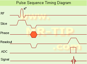
Gradient Echo Sequence Timing Diagram (GRE - sequence) A gradient echo is generated by using a pair of bipolar gradient pulses. In the pulse sequence timing diagram, the basic gradient echo sequence is illustrated. There is no refocusing 180° pulse and the data are sampled during a gradient echo, which is achieved by dephasing the spins with a negatively pulsed gradient before they are rephased by an opposite gradient with opposite polarity to generate the echo.
See also the Pulse Sequence Timing Diagram. There you will find a description of the components.
The excitation pulse is termed the alpha pulse α. It tilts the magnetization by a flip angle α, which is typically between 0° and 90°. With a small flip angle there is a reduction in the value of transverse magnetization that will affect subsequent RF pulses. The flip angle can also be slowly increased during data acquisition (variable flip angle: tilt optimized nonsaturation excitation). The data are not acquired in a steady state, where z-magnetization recovery and destruction by ad-pulses are balanced. However, the z-magnetization is used up by tilting a little more of the remaining z-magnetization into the xy-plane for each acquired imaging line.
Gradient echo imaging is typically accomplished by examining the FID, whereas the read gradient is turned on for localization of the signal in the readout direction. T2* is the characteristic decay time constant associated with the FID. The contrast and signal generated by a gradient echo depend on the size of the longitudinal magnetization and the flip angle. When α = 90° the sequence is identical to the so-called partial saturation or saturation recovery pulse sequence. In standard GRE imaging, this basic pulse sequence is repeated as many times as image lines have to be acquired. Additional gradients or radio frequency pulses are introduced with the aim to spoil to refocus the xy-magnetization at the moment when the spin system is subject to the next α pulse.
As a result of the short repetition time, the z-magnetization cannot fully recover and after a few initial α pulses there is an equilibrium established between z-magnetization recovery and z-magnetization reduction due to the α pulses.
Gradient echoes have a lower SAR, are more sensitive to field inhomogeneities and have a reduced crosstalk, so that a small or no slice gap can be used. In or out of phase imaging depending on the selected TE (and field strength of the magnet) is possible. As the flip angle is decreased, T1 weighting can be maintained by reducing the TR. T2* weighting can be minimized by keeping the TE as short as possible, but pure T2 weighting is not possible. By using a reduced flip angle, some of the magnetization value remains longitudinal (less time needed to achieve full recovery) and for a certain T1 and TR, there exist one flip angle that will give the most signal, known as the "Ernst angle".
Contrast values:
PD weighted: Small flip angle (no T1), long TR (no T1) and short TE (no T2*)
T1 weighted: Large flip angle (70°), short TR (less than 50ms) and short TE
T2* weighted: Small flip angle, some longer TR (100 ms) and long TE (20 ms)

Classification of GRE sequences can be made into four categories:
See also Gradient Recalled Echo Sequence, Spoiled Gradient Echo Sequence, Refocused Gradient Echo Sequence, Ultrafast Gradient Echo Sequence.
 
Images, Movies, Sliders:
 MRI Liver In Phase  Open this link in a new window
    
 MRI Liver Out Of Phase  Open this link in a new window
    
 MVP Parasternal  Open this link in a new window
 Breast MRI Images T1 Pre - Post Contrast  Open this link in a new window
 Circle of Willis, Time of Flight, MIP  Open this link in a new window
    
SlidersSliders Overview

 
spacer

• View the DATABASE results for 'Gradient Echo Sequence' (70).Open this link in a new window

 
Further Reading:
  Basics:
Enhanced Fast GRadient Echo 3-Dimensional (efgre3D) or THRIVE
   by www.mri.tju.edu    
  News & More:
MRI evaluation of fatty liver in day to day practice: Quantitative and qualitative methods
Wednesday, 3 September 2014   by www.sciencedirect.com    
T1rho-prepared balanced gradient echo for rapid 3D T1rho MRI
Monday, 1 September 2008   by www.ncbi.nlm.nih.gov    
MRI Resources 
MRI Accidents - MRI Centers - Education pool - Lung Imaging - Resources - Implant and Prosthesis pool
 
Multi Angle Oblique
 
The multi angle oblique technique gives the ability to display anatomical structures in a variety of planes from the data acquired in just one MRI scan. This technique is useful, for example in lumbar spine MRI obtaining images of each intervertebral disc, individually oriented at a different angle, to better recognize herniation or to compare degenerative changes.
This technique is more difficult in the cervical spine MRI region because of the small vertebra and therefore a short distance between the multi angle oblique planes. In case of too short distance or overlapping slices the crosstalk (artifact) destroys the signal with reduced image quality.
spacer

• View the DATABASE results for 'Multi Angle Oblique' (4).Open this link in a new window

MRI Resources 
MRI Reimbursement - Shielding - Safety Training - IR - Bioinformatics - MRI Technician and Technologist Jobs
 
     1 - 5 (of 5)     
Result Pages : [1]
 Random Page
 
Share This Page
FacebookTwitterLinkedIn

MR-TIP    
Community   
User
Pass
Forgot your UserID/Password ?    


MRI is trending to low field magnets :
reduced costs will lead to this change 
AI will close the gap to high field 
only in remote areas 
is only temporary 
never 

Look
      Ups


MR-TIP.com uses cookies! By browsing MR-TIP.com, you agree to our use of cookies.

Magnetic Resonance - Technology Information Portal
Member of SoftWays' Medical Imaging Group - MR-TIP • Radiology-TIP • Medical-Ultrasound-Imaging • 
Copyright © 2003 - 2024 SoftWays. All rights reserved. [ 21 November 2024]
Terms of Use | Privacy Policy | Advertising
 [last update: 2024-02-26 03:41:00]