| Info
Sheets |
| | | | | | | | | | | | | | | | | | | | | | | | |
 | Out-
side |
| | | | |
|
| | | | | |  | Searchterm 'ffe' was also found in the following services: | | | | |
|  | | | | | |  |
| |
|
Coherent gradient echo sequences can measure the free induction decay ( FID), generated just after each excitation pulse or the echo formed prior to the next pulse. Coherent gradient echo sequences are very sensitive to magnetic field inhomogeneity.
An alternative to spoiling is to incorporate residual transverse magnetization directly into the longitudinal steady state.
These GRE sequences use a refocusing gradient in the phase encoding direction during the end module to maximize remaining transverse (xy) magnetization at the time when the next excitation is due, while the other two gradients are, in any case, balanced.
When the next excitation pulse is sent into the system with an opposed phase, it tilts the magnetization in the - a direction. As a result the z-magnetization is again partly tilted into the xy-plane, while the remaining xy-magnetization is tilted partly into the z-direction.
A fully refocused sequence with a properly selected and uniform f would yield higher signal, especially for tissues with long T2 relaxation times (high water content) so it is used in angiographic, myelographic or arthrographic examinations and is used for T2* weighting.
The repetition time for this sequence has to be short. With short TR, coherent GE is also useable for breath hold and 3D technique. If the repetition time is about 200 msec there's no di fference between spoiled or unspoiled GE. T1 weighting is better with spoiled techniques.
The common types include GRASS, FISP, FAST, and FFE.
The T2* component decreases with long TR and short TE. The T1 time is controlled by flip angle. The common TR is less than 50 ms and the common TE less than 15 ms
Other types have stronger T2 dependence but lower SNR. They include SSFP, CE-FAST, PSIF, and CE- FFE-T2.
Examples of fully refocused FID sequences are TrueFISP, b FFE and bTFE. | | | |
• View the DATABASE results for 'Coherent Gradient Echo' (6).
| | | | |
| | | | | |
| |
|
Contrast enhanced GRE sequences provide T2 contrast but have a relatively poor SNR. Repetitive RF pulses with small flip angles together with appropriate gradient profiles lead to the superposition of two resonance signals.
The first signal is due to the free induction decay FID observed after the first and all ensuing RF excitations.
The second is a resonance signal obtained as a result of a spin echo generated by the second and all addicted RF-pulses.
Hence it is absent after the first excitation, it is a result of the free induction decay of the second to last RF-excitation and has a TE, which is almost 2TR.
For this echo to occur the gradients have to be completely symmetrical relative to the half time between two RF-pulses, a condition that makes it difficult to integrate this pulse sequence into a multiple slice imaging technique.
The second signal not only contains echo contributions from free induction decay, but obviously weakened by T2-decay.
Since the echo is generated by a RF-pulse, it is truly T2 rather than T2* weighted. Correspondingly it is also less sensitive to susceptibility changes and field inhomogeneities.
Companies use di fferent acronyms to describe certain techniques.
Different terms (see also acronyms) for these gradient echo pulse sequences:
CE-FAST Contrast Enhanced Fourier Acquired Steady State,
CE-FFE Contrast Enhanced Fast Field Echo,
CE-GRE Contrast Enhanced Gradient-Echo,
DE-FGR Driven Equilibrium FGR,
FADE FASE Acquisition Double Echo,
PSIF Reverse Fast Imaging with Steady State Precession,
SSFP Steady State Free Precession,
T2 FFE Contrast Enhanced Fast Field Echo (T2 weighted).
In this context, 'contrast enhanced' refers to the pulse sequence, it does not mean enhancement with a contrast agent. | | | |
• View the DATABASE results for 'Contrast Enhanced Gradient Echo Sequence' (4).
| | | | |
| | | Searchterm 'ffe' was also found in the following services: | | | | |
| | |
| |
|
Quantification relies on inflow e ffects or on spin phase e ffects and therefore on quantifying the phase shifts of moving tissues relative to stationary tissues.
With properly designed pulse sequences (see phase contrast sequence) the pixel by pixel phase represents a map of the velocities measured in the imaging plane. Spin phase e ffect-based flow quantification schemes use pulse sequences specifically designed so that the phase angle in a pixel obtained upon measuring the signal is proportional to the velocity. As the relation of the phase angle to the velocity is defined by the gradient amplitudes and the gradient switch-on times, which are known, velocity can be determined quantitatively on a pixel-by-pixel basis. Once, this velocity is known, the flow in a vessel can be determined by multiplying the pixel area with the pixel velocity. Summing this quantity for all pixels inside a vessel results in a flow volume, which is measured, e.g. in ml/sec.
Flow related enhancement-based flow quantification techniques (entry phenomena) work because spins in a section perpendicular to the vessel of interest are labeled with some radio frequency RF pulse. Positional readout of the tagged spins some time T later will show the distance D they have traveled.
For constant flow, the velocity v is obtained by dividing the distance D by the time T : v = D/T. Variations of this basic principle have been proposed to measure flow, but the standard methods to measure velocity and flow use the spin phase effect.
Cardiac MRI sequences are used to encode images with velocity information. These pulse sequences permit quantification of flow-related physiologic data, such as blood flow in the aorta or pulmonary arteries and the peak velocity across stenotic valves. | | | |
• View the DATABASE results for 'Flow Quantification' (6).
| | | | |
| | | | | |
| |
|
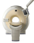
From Philips Medical Systems;
The clinical capabilities of MR will further expand. Inside and out, the Achieva is a friendly, open system designed for optimal patient comfort and maximized workflow with high functionality.
The Achieva 1.5T can be upgraded to Achieva I/T, with three configurations optimized for MR guided interventions and therapy:
•
Achieva I/T Neurosurgery
•
Achieva I/T Cardiovascular (or XMR - combining an Achieva 1.5T CV system and an X-Ray system)
Device Information and Specification
CLINICAL APPLICATION
Whole body
CONFIGURATION
Short bore compact
Standard: Head, body, C1, C3; Optional: Small joint, flex-E, flex-R, endocavitary (L and S), dual TMJ, knee, neck, T/L spine, breast; optional phased array: Spine, pediatric, 3rd party connector; Optional SENSEâ„¢ coils for all applications
SE, Modified-SE, IR (T1, T2, PD), STIR, FLAIR, SPIR, FFE, T1- FFE, T2- FFE, Balanced FFE, TFE, Balanced TFE, Dynamic, Keyhole, 3D, Multi Chunk 3D, Multi Stack 3D, K Space Shutter, MTC, TSE, Dual IR, DRIVE, EPI, Cine, 2DMSS, DAVE, Mixed Mode; Angiography: Inflow MRA, TONE, PCA, CE MRA
128 x 128, 256 x 256,512 x 512,1024 x 1024 (64 for Bold img)
Variable in 1% increments
Lum.: 120 cd/m2; contrast: 150:1
Variable (op. param. depend.)
POWER REQUIREMENTS
380/400 V
| | | |
• View the DATABASE results for 'Intera Achieva 1.5T™' (2).
| | | | |
| | | | |
| | |
| | | |
|
| |
 | Look
Ups |
| |