Magnetic Resonance - Technology Information Portal Welcome to MRI Technology
Info
  Sheets

Out-
      side


 'main magnetic field strength' 
SEARCH FOR    
 
  2 3 5 A B C D E F G H I J K L M N O P Q R S T U V W X Y Z
Result : Searchterm 'main magnetic field strength' found in 0 term [] and 1 definition [], (+ 20 Boolean[] results
1 - 5 (of 21)     next
Result Pages : [1]  [2 3 4 5]
Searchterm 'main magnetic field strength' was also found in the following service: 
spacer
News  (1)  
 
B0
 
[B0] A conventional symbol for the main magnetic field strength (magnetic flux density or induction) in a MRI system. Although historically used, H0 (units of magnetic field strength, ampere//meter) should be distinguished from the more appropriate B0 [units of magnetic induction, tesla].
In current MR systems it has a constant value over time varying from 0.02 to 4 T. Field strengths of 0.5 T and above are generated with superconductive magnets. High field strengths have a better signal to noise ratio (SNR). The optimal imaging field strength for clinical imaging is between 0.5 and 2.0 T.

See also the related poll result: 'In 2010 your scanner will probably work with a field strength of'
spacer
 
• Share the entry 'B0':  Facebook  Twitter  LinkedIn  
 
Further Reading:
  Basics:
Factors influencing flip angle mapping in MRI: RF pulse shape, slice-select gradients, off-resonance excitation, and B0 inhomogeneities.
Tuesday, 1 August 2006   by www.ncbi.nlm.nih.gov    
Magnetic Field
   by hyperphysics.phy-astr.gsu.edu    
  News & More:
Turbo-FLASH Based Arterial Spin Labeled Perfusion MRI at 7 T
Thursday, 20 June 2013   by www.plosone.org    
Penn researchers to get 7 Tesla whole-body MRI system
Monday, 28 August 2006   by www.eurekalert.org    
Optimizing SPIR and SPAIR fat suppression
Tuesday, 30 November 2004   by clinical.netforum.healthcare.philips.com    
MRI Resources 
Used and Refurbished MRI Equipment - Movies - Collections - Claustrophobia - MRI Training Courses - Homepages
 
ARTOSCANâ„¢ - MInfoSheet: - Devices -
Intro, 
Types of Magnets, 
Overview, 
etc.MRI Resource Directory:
 - Devices -
 
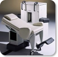
www.gemedicalsystems.com/rad/mri/products/artoscan/specs.html Developed by GE Lunar; the ARTOSCANâ„¢-M is designed specifically for in-office musculoskeletal imaging. ARTOSCAN-M's compact, modular design allows placing within a clinical environment, bringing MRI to the patient. Patients remain outside the magnet at all times during the examinations, enabling constant patient-technologist contact. ARTOSCAN-M requires no special RF room, magnetic shielding, special power supply or air conditioning.
The C-SCANâ„¢ (also known as Artoscan C) is developed from the ARTOSCANâ„¢ - M, with a new computer platform.
Device Information and Specification
CLINICAL APPLICATION
Dedicated extremity
CONFIGURATION
Closed
Linear and dual phased array coil, knee, ankle, wrist coils
PULSE SEQUENCES
SE, GE, IR, STIR, FSE, 3D CE, GE-STIR, 3D GE, ME, TME, HSE
IMAGING MODES
Single, multislice, volume study, fast scan, multi slab, cine
TR
12 - 5,000 msec
TE
5 - 220 msec
SINGLE SLICE
0.8 sec/image
MULTISLICE
0.8 sec/image
FOV
10 - 20 cm
SLICE THICKNESS
2D: 2 mm - 10 mm;
3D: 0.6 mm - 10 mm
512 x 512
MEASURING MATRIX
256 x 256 maximum
PIXEL INTENSITY
4,096 gray lvls, 256 lvls in 3D
MAGNET TYPE
Ferrite Permanent
MAGNET WEIGHT
965 kg
POWER REQUIREMENTS
100/110/200/220/230/240V
STRENGTH
10 mT/m
5 GAUSS FRINGE FIELD, radial/axial
28 cm/60 cm
Passive
spacer

• View the DATABASE results for 'ARTOSCAN™ - M' (3).Open this link in a new window

MRI Resources 
Pathology - Examinations - MRI Training Courses - Raman Spectroscopy - Cochlear Implant - Lung Imaging
 
Signa HDx 1.5Tâ„¢InfoSheet: - Devices -
Intro, 
Types of Magnets, 
Overview, 
etc.
 
www.vitalcom.com/euen/mri/products/signa-hdx-15t/index.html From GE Healthcare;
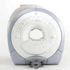
The GE Signa HDx MRI system is a whole body magnetic resonance scanner designed to support high resolution, high signal to noise ratio, and short scan times.
The 1.5T Signa HDx MR Systems is a modification of the currently marketed GE 1.5T machines, with the main difference being the change to the receive chain architecture that includes a thirty two independent receive channels, and allows for future expansion in 16 channel increments. The overall system has been improved with a simplified user interface and a single 23" liquid crystal display, improved multi channel surface coil connectivity, and an improved image reconstruction architecture known as the Volume Recon Engine (VRE).
Device Information and Specification
CLINICAL APPLICATION
Whole body
CONFIGURATION
Compact short bore
Possible
SYNCHRONIZATION
ECG/peripheral, respiratory gating, (SmartPrep, SmartStep)
PULSE SEQUENCES
Standard: SE, IR, 2D/3D GRE and SPGR, Angiography: 2D/3D TOF, 2D/3D Phase Contrast; 2D/3D FSE, 2D/3D FGRE and FSPGR, SSFP, FLAIR, EPI, optional: 2D/3D Fiesta, FGRET, Spiral, Tensor,
IMAGING MODES
2D single slice, multi slice, and 3D volume images, multi slab, cine
1 cm to 48 cm continuous
2D 0.7 mm to 20 mm; 3D 0.1 mm to 5 mm
1028 x 1024
MEASURING MATRIX
128x512 steps 32 phase encode
PIXEL INTENSITY
256 gray levels
POWER REQUIREMENTS
480 or 380/415
COOLING SYSTEM TYPE
Closed-loop water-cooled gradient
CRYOGEN USE, L/hr
less than 0.03 L/hr liquid helium
spacer
Searchterm 'main magnetic field strength' was also found in the following service: 
spacer
News  (1)  
 
Chemical Shift ArtifactInfoSheet: - Artifacts - 
Case Studies, 
Reduction Index, 
etc.MRI Resource Directory:
 - Artifacts -
 
Quick Overview
Please note that there are different common names for this artifact.
Artifact Information
NAME
Chemical shift, black boundary, spatial misregistration, relief
DESCRIPTION
Black or bright band
During frequency encoding, fat protons precess slower than water protons in the same slice because of their magnetic shielding. Through the difference in resonance frequency between water and fat, protons at the same location are misregistrated (dislocated) by the Fourier transformation, when converting MRI signals from frequency to spatial domain. This chemical shift misregistration cause accentuation of any fat-water interfaces along the frequency axis and may be mistaken for pathology. Where fat and water are in the same location, this artifact can be seen as a bright or dark band at the edge of the anatomy.
Protons in fat and water molecules are separated by a chemical shift of about 3.5 ppm. The actual shift in Hertz (Hz) depends on the magnetic field strength of the magnet being used. Higher field strength increases the misregistration, while in contrast a higher gradient strength has a positive effect. For a 0.3 T system operating at 12.8 MHz the shift will be 44.8 Hz compared with a 223.6 Hz shift for a 1.5 T system operating at 63.9 MHz.
mri safety guidance
Image Guidance
For artifact reduction helps a smaller water fat shift (higher bandwidth), a higher matrix, an in phase TE or a spin echo technique. Since the misregistration offset is present in the read out axis the patient may be rescanned with this axis parallel to the fat-water interface. Steeper gradient may be employed to reduce the chemical shift offset in mm. Another strategy is to employ specialized pulse sequences such as fat saturation or inversion recovery imaging. Fat suppression techniques eliminate chemical shift artifacts caused by the lack of fat signal.

See also Black Boundary Artifact and Magnetic Resonance Spectroscopy.
spacer

• View the DATABASE results for 'Chemical Shift Artifact' (7).Open this link in a new window

 
Further Reading:
  Basics:
MRI Artifact Gallery
   by chickscope.beckman.uiuc.edu    
  News & More:
What is chemical shift artefact? Why does it occur? How many Hz at 1.5 T?
   by www.revisemri.com    
Abdominal MRI at 3.0 T: The Basics Revisited
Wednesday, 20 July 2005   by www.ajronline.org    
MRI Resources 
Pregnancy - Portals - Chemistry - Contrast Agents - Implant and Prosthesis pool - Services and Supplies
 
MRI SafetyMRI Resource Directory:
 - Safety -
 
There are different types of contraindications that would prevent a person from being examined with an MRI scanner. MRI systems use strong magnetic fields that attract any ferromagnetic objects with enormous force. Caused by the potential risk of heating, produced from the radio frequency pulses during the MRI procedure, metallic objects like wires, foreign bodies and other implants needs to be checked for compatibility. High field MRI requires particular safety precautions. In addition, any device or MRI equipment that enters the magnet room has to be MR compatible. MRI examinations are safe and harmless, if these MRI risks are observed and regulations are followed.

Safety concerns in magnetic resonance imaging include:
•
the magnetic field strength;
•
possible 'missile effects' caused by magnetic forces;
•
the potential for heating of body tissue due to the application of the radio frequency energy;
•
the effects on implanted active devices such as cardiac pacemakers or insulin pumps;
•
magnetic torque effects on indwelling metal (clips, etc.);
•
the audible acoustic noise;
•
danger due to cryogenic liquids;
•
the application of contrast medium;
mri safety guidance
MRI Safety Guidance
It is important to remember when working around a superconducting magnet that the magnetic field is always on. Under usual working conditions the field is never turned off. Attention must be paid to keep all ferromagnetic items at an adequate distance from the magnet. Ferromagnetic objects which came accidentally under the influence of these strong magnets can injure or kill individuals in or nearby the magnet, or can seriously damage every hardware, the magnet itself, the cooling system, etc.. See MRI resources Accidents.
The doors leading to a magnet room should be closed at all times except when entering or exiting the room. Every person working in or entering the magnet room or adjacent rooms with a magnetic field has to be instructed about the dangers. This should include the patient, intensive-care staff, and maintenance-, service- and cleaning personnel, etc..
The 5 Gauss limit defines the 'safe' level of static magnetic field exposure. The value of the absorbed dose is fixed by the authorities to avoid heating of the patient's tissue and is defined by the specific absorption rate. Leads or wires that are used in the magnet bore during imaging procedures, should not form large-radius wire loops. Leg-to-leg and leg-to-arm skin contact should be prevented in order to avoid the risk of burning due to the generation of high current loops if the legs or arms are allowed to touch. The patient's skin should not be in contact with the inner bore of the magnet.
The outflow from cryogens like liquid helium is improbable during normal operation and not a real danger for patients.
The safety of MRI contrast agents is tested in drug trials and they have a high compatibility with very few side effects. The variations of the side effects and possible contraindications are similar to X-ray contrast medium, but very rare. In general, an adverse reaction increases with the quantity of the MRI contrast medium and also with the osmolarity of the compound.

See also 5 Gauss Fringe Field, 5 Gauss Line, Cardiac Risks, Cardiac Stent, dB/dt, Legal Requirements, Low Field MRI, Magnetohydrodynamic Effect, MR Compatibility, MR Guided Interventions, Claustrophobia, MRI Risks and Shielding.
Radiology-tip.comradRadiation Safety,  Ionizing Radiation
spacer
Medical-Ultrasound-Imaging.comUltrasound Safety,  Absorbed Dose
spacer

• View the DATABASE results for 'MRI Safety' (42).Open this link in a new window


• View the NEWS results for 'MRI Safety' (13).Open this link in a new window.
 
Further Reading:
  Basics:
MRI Safety
2001   by www.fda.gov    
What MRI Sequences Produce the Highest Specific Absorption Rate (SAR), and Is There Something We Should Be Doing to Reduce the SAR During Standard Examinations?
Thursday, 16 April 2015   by www.ajronline.org    
Contrast Agents: Safety Profile
   by www.clinical-mri.com    
  News & More:
How safe is 7T MRI for patients with neurosurgical implants?
Thursday, 17 November 2022   by healthimaging.com    
Newer Heart Devices Safe During MRI
Monday, 23 August 2004   by www.hospimedica.com    
Study: Face Masks Unsafe in MRI Machines
Wednesday, 13 July 2022   by www.laboratoryequipment.com    
COVID-19: Attention shifts to MRI infection control
Thursday, 9 July 2020   by https://www.auntminnieeurope.com/index.aspx?sec=ser§sub=def§pag=dis§ItemID=619012    
FDA Releases New Guidance On Establishing Safety, Compatibility Of Passive Implants In MR Environments
Tuesday, 16 December 2014   by www.meddeviceonline.com    
Modern Implantable Heart Devices Safe For Use In MRI Scans
Wednesday, 16 March 2005   by www.sciencedaily.com    
MRI Resources 
Pediatric and Fetal MRI - Safety Products - Homepages - Spectroscopy - Portals - Shoulder MRI
 
     1 - 5 (of 21)     next
Result Pages : [1]  [2 3 4 5]
 Random Page
 
Share This Page
FacebookTwitterLinkedIn

MR-TIP    
Community   
User
Pass
Forgot your UserID/Password ?    


Personalized protocols (age, gender, body habitus, etc.) lead to :
more automated planning 
improved patient comfort 
better diagnostics 
optimized image quality 
nothing 

Look
      Ups


MR-TIP.com uses cookies! By browsing MR-TIP.com, you agree to our use of cookies.

Magnetic Resonance - Technology Information Portal
Member of SoftWays' Medical Imaging Group - MR-TIP • Radiology-TIP • Medical-Ultrasound-Imaging • 
Copyright © 2003 - 2024 SoftWays. All rights reserved. [ 21 November 2024]
Terms of Use | Privacy Policy | Advertising
 [last update: 2024-02-26 03:41:00]