| Info
Sheets |
| | | | | | | | | | | | | | | | | | | | | | | | |
 | Out-
side |
| | | | |
|
| | | | |
Result : Searchterm 'pixel size' found in 0 term [ ] and 1 definition [ ] and 1 definition [ ], (+ 11 Boolean[ ], (+ 11 Boolean[ ] results ] results
| | 1 - 5 (of 12) nextResult Pages : [1] [2 3] |  | |  | Searchterm 'pixel size' was also found in the following service: | | | | |
| |  |
| |
|
The image resolution is the level of detail of an image and a measurement of image quality. Higher resolution means more image detail, for example when two structures 1 mm apart are distinguishable in an image, this picture has a higher resolution than an image where they are not to distinguish.
More data points in an MR image (with same FOV) will decrease the pixel size, but not accurately improve the resolution because the different MRI sequences influence the contrast and the discernment of different tissues.
With high contrast and optimal signal to noise ratio, the image resolution is depend on FOV and number of data points of a picture, but T2* effects have an additional influence. | | | | | | • Share the entry 'Image Resolution':    | | |
• View the NEWS results for 'Image Resolution' (1).
| | | | |  Further Reading: Further Reading: | | Basics:
|
|
News & More:
| |
| |
| | | | |  |
| |
|
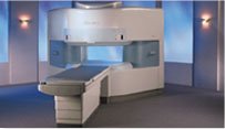
From Hitachi Medical Systems America, Inc.;
the AIRIS made its debut in 1995. Hitachi followed up with the AIRIS II system, which has proven equally successfully. 'All told, Hitachi has installed more than 1,000 MRI systems in the U.S., holding more than 17 percent of the total U.S. MRI installed base, and more than half of the installed base of open MR systems,' says Antonio Garcia, Frost and Sullivan industry research analyst.
Now Altaire employs a blend of innovative Hitachi features called VOSI™ technology, optimizing each sub-system's performance in concert with the
other sub-systems, to give the seamless mix of high-field performance
and the patient comfort, especially for claustrophobic patients, of open MR systems.
Device Information and Specification
CLINICAL APPLICATION
Whole body
DualQuad T/R Body Coil, MA Head, MA C-Spine, MA Shoulder, MA Wrist, MA CTL Spine, MA Knee, MA TMJ, MA Flex Body (3 sizes), Neck, small and large Extremity, PVA (WIP), Breast (WIP), Neurovascular (WIP), Cardiac (WIP) and MA Foot//Ankle (WIP)
SE, GE, GR, IR, FIR, STIR, ss-FSE, FSE, DE-FSE/FIR, FLAIR, ss/ms-EPI, ss/ms EPI- DWI, SSP, MTC, SE/GE-EPI, MRCP, SARGE, RSSG, TRSG, BASG, Angiography: CE, PC, 2D/3D TOF
IMAGING MODES
Single, multislice, volume study
TR
SE: 30 - 10,000msec GE: 3.6 - 10,000msec IR: 50 - 16,700msec FSE: 200 - 16,7000msec
TE
SE : 8 - 250msec IR: 5.2 -7,680msec GE: 1.8 - 2,000 msec FSE: 5.2 - 7,680
0.05 sec/image (256 x 256)
2D: 2 - 100 mm; 3D: 0.5 - 5 mm
Level Range: -2,000 to +4,000
COOLING SYSTEM TYPE
Water-cooled
3.1 m lateral, 3.6 m vertical
| | | |
• View the DATABASE results for 'Altaire™' (2).
| | | | | | Further Reading: | News & More:
|
|
| |
| | | | | |
| |
|
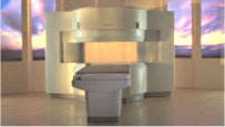
From Hitachi Medical Systems America Inc.;
the AIRIS II, an entry in the diagnostic category of open MR systems, was designed by Hitachi
Medical Systems America Inc. (Twinsburg, OH, USA) and Hitachi Medical Corp. (Tokyo) and is manufactured by the Tokyo branch. A 0.3 T field-strength magnet and phased array coils deliver high image quality without the need for a tunnel-type high-field system, thereby significantly improving patient comfort not only for claustrophobic patients.
Device Information and Specification
CLINICAL APPLICATION
Whole body
QD Head, MA Head and Neck, QD C-Spine, MA or QD Shoulder, MA CTL Spine, QD Knee, Neck, QD TMJ, QD Breast, QD Flex Body (4 sizes), Small and Large Extrem., QD Wrist, MA Foot and Ankle (WIP), PVA (WIP)
SE, GE, GR, IR, FIR, STIR, FSE, ss-FSE, FLAIR, EPI -DWI, SE-EPI, ms - EPI, SSP, MTC, SARGE, RSSG, TRSG, MRCP, Angiography: CE, 2D/3D TOF
IMAGING MODES
Single, multislice, volume study
TR
SE: 30 - 10,000msec GE: 20 - 10,000msec IR: 50 - 16,700msec FSE: 200 - 16,7000msec
TE
SE : 10 - 250msec IR: 10 -250msec GE: 5 - 50 msec FSE: 15 - 2,000
0.05 sec/image (256 x 256)
2D: 2 - 100 mm; 3D: 0.5 - 5 mm
Level Range: -2,000 to +4,000
POWER REQUIREMENTS
208/220/240 V, single phase
COOLING SYSTEM TYPE
Air-cooled
2.0 m lateral, 2.5 m vert./long
| | | |
• View the DATABASE results for 'AIRIS II™' (2).
| | | | |
| | | Searchterm 'pixel size' was also found in the following service: | | | | |
| | |
| |
|
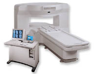
From GE Healthcare;
the New Signa Profile/i is a patient friendly open MRI system that virtually eliminates patient anxiety and claustrophobia, without compromising diagnostic utility.
Device Information and Specification CLINICAL APPLICATION Whole body Integrated transmit body coil, body flex sizes: M, L, XL, quadrature, head coil quadrature, 4 channel neurovascular array, 8 channel CTL array, quad. c- spine, 2 channel shoulder array, extremity coil, 3 channel wrist array, 4 channel breast array, 6, 9, 11 inch general purpose loop coils Standard: SE, IR, 2D/3D GRE and SPGR, Angiography: 2D/3D TOF, 2D/3D phase contrast; 2D/3D FSE, 2D/3D FRFSE, FGRE and FSPGR, SSFP, FLAIR, EPI, optional: 2D/3D Fiesta, fat/water separation, T1 FLAIRIMAGING MODES Localizer, single slice, multislice, volume, fast, POMP, multi slab, cine, slice and frequency zip, extended dynamic range, tailored RF TR 6 to 12000 msec in increments of 1 msec TE 1.3 to 2000 msec in increments of 1 msec 2D: 2.7mm - 20mm 3D: 0.2mm - 5mm 0.08 mm; 0.02 mm optional 10,000 kg w/gradient enclosure POWER REQUIREMENTS 200 - 480, 3-phase COOLING SYSTEM TYPE None required | | | |
• View the DATABASE results for 'Signa Profile™' (2).
| | | | |
| | | | | |
| |
|
(PC) Phase contrast sequences are the basis of MRA techniques utilizing the change in the phase shifts of the flowing protons in the region of interest to create an image. Spins that are moving along the direction of a magnetic field gradient receive a phase shift proportional to their velocity.
In a phase contrast sequence two data sets with a different amount of flow sensitivity are acquired. This is usually accomplished by applying gradient pairs, which sequentially dephase and then rephase spins during the sequence. Both 2D and 3D acquisition techniques can be applied with phase contrast MRA.
The first data set is acquired with a flow compensated sequence, i. e. without flow sensitivity. The second data set is acquired with a flow sensitive sequence. The amount of flow sensitivity is controlled by the strength of the bipolar gradient pulse pair, which is incorporated into the sequence. Stationary tissue undergoes no effective phase change after the application of the two gradients. Caused by the different spatial localization of flowing blood to stationary tissue, it experiences a different size of the second bipolar gradient compared to the first. The result is a phase shift.
The raw data from the two data sets are subtracted. By comparing the phase of signals from each location in the two sequences the exact amount of motion induced phase change can be determined to have a map where pixel brightness is proportional to spatial velocity.
Phase contrast images represent the signal intensity of the velocity of spins at each point within the field of view. Regions that are stationary remain black while moving regions are represented as grey to white.
The phase shift is proportional to the spin's velocity, and this allows the quantitative assessment of flow velocities.
The difference MRI signal has a maximum value for opposite directions. This velocity is typically referred to as venc, and depends on the pulse amplitude and distance between the gradient pulse pair. For velocities larger than venc the difference signal is decreased constantly until it gets zero. Therefore, in a phase contrast angiography it is important to correctly set the venc of the sequence to the maximum flow velocity which is expected during the measurement. High venc factors of the PC angiogram (more than 40 cm/sec) will selectively image the arteries ( PCA - arteriography), whereas a venc factor of 20 cm/sec will perform the veins and sinuses (PCV or MRV - venography).
See also Flow Quantification, Contrast Enhanced MR Venography, Time of Flight Angiography, Time Resolved Imaging of Contrast Kinetics. | | | | | |
• View the DATABASE results for 'Phase Contrast Sequence' (5).
| | | | | | Further Reading: | Basics:
|
|
| |
| | | | |
| | | 1 - 5 (of 12) nextResult Pages : [1] [2 3] |
| |
|
| |
 | Look
Ups |
| |