Magnetic Resonance - Technology Information Portal Welcome to MRI Technology
Info
  Sheets

Out-
      side


 'Magnetization Value' 
SEARCH FOR    
 
  2 3 5 A B C D E F G H I J K L M N O P Q R S T U V W X Y Z
Result : Searchterm 'Magnetization Value' found in 1 term [] and 3 definitions [], (+ 17 Boolean[] results
previous     6 - 10 (of 21)     next
Result Pages : [1]  [2 3 4 5]
MRI Resources 
Safety pool - Absorption and Emission - Breast Implant - Hospitals - Research Labs - Pacemaker
 
Inversion Recovery SequenceForum -
related threadsInfoSheet: - Sequences - 
Intro, 
Overview, 
Types of, 
etc.
 
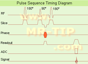
Inversion Recovery Sequence Timing Diagram (IR) The inversion recovery pulse sequence produces signals, which represent the longitudinal magnetization existing after the application of a 180° radio frequency pulse that rotates the magnetization Mz into the negative plane. After an inversion time (TI - time between the starting 180° pulse and the following 90° pulse), a further 90° RF pulse tilts some or all of the z-magnetization into the xy-plane, where the signal is usually rephased with a 180° pulse as in the spin echo sequence. During the initial time period, various tissues relax with their intrinsic T1 relaxation time.
In the pulse sequence timing diagram, the basic inversion recovery sequence is illustrated. The 180° inversion pulse is attached prior to the 90° excitation pulse of a spin echo acquisition. See also the Pulse Sequence Timing Diagram. There you will find a description of the components.
The inversion recovery sequence has the advantage, that it can provide very strong contrast between tissues having different T1 relaxation times or to suppress tissues like fluid or fat. But the disadvantage is, that the additional inversion radio frequency RF pulse makes this sequence less time efficient than the other pulse sequences.

Contrast values:
PD weighted: TE: 10-20 ms, TR: 2000 ms, TI: 1800 ms
T1 weighted: TE: 10-20 ms, TR: 2000 ms, TI: 400-800 ms
T2 weighted: TE: 70 ms, TR: 2000 ms, TI: 400-800 ms

See also Inversion Recovery, Short T1 Inversion Recovery, Fluid Attenuation Inversion Recovery, and Acronyms for 'Inversion Recovery Sequence' from different manufacturers.
 
Images, Movies, Sliders:
 Brain MRI Inversion Recovery  Open this link in a new window
    
 Knee MRI Sagittal STIR 002  Open this link in a new window
 Brain MRI Coronal FLAIR 001  Open this link in a new window
    
 
spacer
 
• Related Searches:
    • Short T1 Inversion Recovery
    • Flow Sensitive Alternating Inversion Recovery
    • Saturation Pulses
    • Double Inversion Recovery T1 Measurement
    • Fluid Attenuation Inversion Recovery
 
Further Reading:
  Basics:
The equation for a repeated inversion recovery sequence
Contrast mechanisms in magnetic resonance imaging
2004   by www.iop.org    
  News & More:
FLAIR Vascular Hyperintensity: An Important MRI Marker in Patients with Transient Ischemic Attack
Thursday, 14 July 2022   by www.dovepress.com    
MRI Resources 
Non-English - Stimulator pool - MRI Centers - MRCP - MRI Reimbursement - Databases
 
Balanced Fast Field EchoInfoSheet: - Sequences - 
Intro, 
Overview, 
Types of, 
etc.MRI Resource Directory:
 - Sequences -
 
(bFFE) A FFE sequence using a balanced gradient waveform. A balanced sequence starts out with a RF pulse of 90° or less and the spins in the steady state. Before the next TR in the slice phase and frequency encoding, gradients are balanced so their net value is zero. Now the spins are prepared to accept the next RF pulse, and their corresponding signal can become part of the new transverse magnetization. Since the balanced gradients maintain the transverse and longitudinal magnetization, the result is, that both T1 and T2 contrast are represented in the image. This pulse sequence produces images with increased signal from fluid, along with retaining T1 weighted tissue contrast. Because this form of sequence is extremely dependent on field homogeneity, it is essential to run a shimming prior the acquisition. A fully balanced (refocused) sequence would yield higher signal, especially for tissues with long T2 relaxation times.

See Steady State Free Precession and Gradient Echo Sequence.
 
Images, Movies, Sliders:
 Cardiac Infarct Short Axis Cine bFFE 1  Open this link in a new window
    
 
spacer

• View the DATABASE results for 'Balanced Fast Field Echo' (3).Open this link in a new window

 
Further Reading:
  News & More:
T1rho-prepared balanced gradient echo for rapid 3D T1rho MRI
Monday, 1 September 2008   by www.ncbi.nlm.nih.gov    
Utility of the FIESTA Pulse Sequence in Body Oncologic Imaging: Review
June 2009   by www.ajronline.org    
MRI Resources 
Safety pool - Calculation - MRI Physics - Universities - Spectroscopy - DICOM
 
Fast Low Angle ShotInfoSheet: - Sequences - 
Intro, 
Overview, 
Types of, 
etc.MRI Resource Directory:
 - Sequences -
 
(FLASH) A fast sequence producing signals called gradient echo with low flip angles. FLASH sequences are modifications, which incorporate or remove the effects of transverse coherence respectively.
FLASH uses a semi-random spoiler gradient after each echo to spoil the steady state (to destroy any remaining transverse magnetization) by causing a spatially dependent phase shift. The transverse steady state is spoiled but the longitudinal steady state depends on the T1 values and the flip angle. Extremely short TR times are possible, as a result the sequence provides a mechanism for gaining extremely high T1 contrast by imaging with TR times as brief as 20 to 30 msec while retaining reasonable signal levels. It is important to keep the TE as short as possible to suppress susceptibility artifacts.
The T1 contrast depends on the TR as well as on flip angle, with short TE.
Small flip angles and short TR results in proton density, and long TR in T2* weighting.
With large flip angles and short TR result T1 weighted images.

TR and flip angle adjustment:

TR 3000 ms, Flip Angle 90°
TR 1500 ms, Flip Angle 45°
TR 700 ms, Flip Angle 25°
TR 125 ms, Flip Angle 10°

The apparent ability to trade TR against flip angle for purposes of contrast and the variation in SNR as the scan time (TR) is reduced.

See also Gradient Echo Sequence.
 
Images, Movies, Sliders:
 Fetus (Brain) and Dermoid in Mother  Open this link in a new window
      

Courtesy of  Robert R. Edelman

 
spacer

• View the DATABASE results for 'Fast Low Angle Shot' (5).Open this link in a new window

 
Further Reading:
  News & More:
Motion Compensation in MR Imaging
   by ccn.ucla.edu    
Turbo-FLASH Based Arterial Spin Labeled Perfusion MRI at 7 T
Thursday, 20 June 2013   by www.plosone.org    
Usefulness of MR Imaging for Diseases of the Small Intestine: Comparison with CT
2000   by www.ncbi.nlm.nih.gov    
MRI Resources 
Nerve Stimulator - Safety Training - MRI Accidents - Equipment - Universities - Fluorescence
 
Image Selected In Vivo Spectroscopy
 
(ISIS) Image selected in vivo spectroscopy is used as a localization sequence to provide complete gradient controlled three-dimensional localization with a reduced number of sequence cycles, e.g. for in vivo 31P spectroscopy. The ISIS method generates three 180° pulses prior to a 90° pulse, after which the free induction decay is recorded. Specific 180° pulses (slice-selective) are combined and the FID's added or subtracted to generate a spectrum.
An advantage of the ISIS method is that the magnetization (before the final 90° pulse) is predominantly along the z-axis and so T2 effects are relatively small. This explains the value of this technique for 31P data acquisition, because some phosphorus metabolites (e.g. ATP) have short T2 values.
A disadvantage is that eight acquisitions are required to accomplish the spatial localization, therefore the sequence cannot be used for localized shimming. Another problem, because any variation between these data collections (for example, due to movement) will degrade these applications, can be solved by incorporating outer volume suppression techniques such as OSIRIS (modified ISIS).
spacer
MRI Resources 
Jobs - Pacemaker - Raman Spectroscopy - Libraries - Shielding - Societies
 
Magnetization Transfer Contrast
 
(MTC) This MRI method increases the contrast by removing a portion of the total signal in tissue. An off resonance radio frequency (RF) pulse saturates macromolecular protons to make them invisible (caused by their ultra-short T2* relaxation times). The MRI signal from semi-solid tissue like brain parenchyma is reduced, and the signal from a more fluid component like blood is retained.
E.g., saturation of broad spectral lines may produce decreases in intensity of lines not directly saturated, through exchange of magnetization between the corresponding states; more closely coupled states will show a greater resulting intensity change. Magnetization transfer techniques make demyelinated brain or spine lesions (as seen e.g. in multiple sclerosis) better visible on T2 weighted images as well as on gadolinium contrast enhanced T1 weighted images.
Off resonance makes use of a selection gradient during an off resonance MTC pulse. The gradient has a negative offset frequency on the arterial side of the imaging volume (caudally more off resonant and cranially less off resonant). The net effect of this type of pulse is that the arterial blood outside the imaging volume will retain more of its longitudinal magnetization, with more vascular signal when it enters the imaging volume. Off resonance MTC saturates the venous blood, leaving the arterial blood untouched.
On resonance has no effect on the free water pool but will saturate the bound water pool and is the difference in T2 between the pools. Special binomial pulses are transmitted causing the magnetization of the free protons to remain unchanged. The z-magnetization returns to its original value. The spins of the bound pool with a short T2 experience decay, resulting in a destroyed magnetization after the on resonance pulse.

See also Magnetization Transfer.
spacer

• View the DATABASE results for 'Magnetization Transfer Contrast' (5).Open this link in a new window

 
Further Reading:
  News & More:
MRI of the Human Eye Using Magnetization Transfer Contrast Enhancement
   by www.iovs.org    
MRI Resources 
Abdominal Imaging - MRI Accidents - Case Studies - Guidance - Most Wanted - Non-English
 
previous      6 - 10 (of 21)     next
Result Pages : [1]  [2 3 4 5]
 Random Page
 
Share This Page
FacebookTwitterLinkedIn

MR-TIP    
Community   
User
Pass
Forgot your UserID/Password ?    


Personalized protocols (age, gender, body habitus, etc.) lead to :
more automated planning 
improved patient comfort 
better diagnostics 
optimized image quality 
nothing 

Look
      Ups


MR-TIP.com uses cookies! By browsing MR-TIP.com, you agree to our use of cookies.

Magnetic Resonance - Technology Information Portal
Member of SoftWays' Medical Imaging Group - MR-TIP • Radiology-TIP • Medical-Ultrasound-Imaging • 
Copyright © 2003 - 2024 SoftWays. All rights reserved. [ 23 November 2024]
Terms of Use | Privacy Policy | Advertising
 [last update: 2024-02-26 03:41:00]