Magnetic Resonance - Technology Information Portal Welcome to MRI Technology
Info
  Sheets

Out-
      side


 'Magnetization Value' 
SEARCH FOR    
 
  2 3 5 A B C D E F G H I J K L M N O P Q R S T U V W X Y Z
Result : Searchterm 'Magnetization Value' found in 1 term [] and 3 definitions [], (+ 17 Boolean[] results
1 - 5 (of 21)     next
Result Pages : [1]  [2 3 4 5]
MRI Resources 
Open Directory Project - Mobile MRI Rental - Examinations - Image Quality - Pathology - MRI Reimbursement
 
Magnetization Value
 
(Mo) Equilibrium value of the magnetization;; directed along the direction of the static magnetic field. Proportional to spin density (N).
spacer
 
• Share the entry 'Magnetization Value':  Facebook  Twitter  LinkedIn  
MRI Resources 
Bioinformatics - MRI Physics - MRI Technician and Technologist Career - Blood Flow Imaging - General - MRI Reimbursement
 
Gradient Echo SequenceForum -
related threadsInfoSheet: - Sequences - 
Intro, 
Overview, 
Types of, 
etc.
 
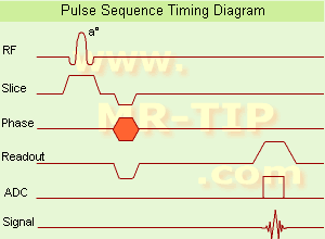
Gradient Echo Sequence Timing Diagram (GRE - sequence) A gradient echo is generated by using a pair of bipolar gradient pulses. In the pulse sequence timing diagram, the basic gradient echo sequence is illustrated. There is no refocusing 180° pulse and the data are sampled during a gradient echo, which is achieved by dephasing the spins with a negatively pulsed gradient before they are rephased by an opposite gradient with opposite polarity to generate the echo.
See also the Pulse Sequence Timing Diagram. There you will find a description of the components.
The excitation pulse is termed the alpha pulse α. It tilts the magnetization by a flip angle α, which is typically between 0° and 90°. With a small flip angle there is a reduction in the value of transverse magnetization that will affect subsequent RF pulses. The flip angle can also be slowly increased during data acquisition (variable flip angle: tilt optimized nonsaturation excitation). The data are not acquired in a steady state, where z-magnetization recovery and destruction by ad-pulses are balanced. However, the z-magnetization is used up by tilting a little more of the remaining z-magnetization into the xy-plane for each acquired imaging line.
Gradient echo imaging is typically accomplished by examining the FID, whereas the read gradient is turned on for localization of the signal in the readout direction. T2* is the characteristic decay time constant associated with the FID. The contrast and signal generated by a gradient echo depend on the size of the longitudinal magnetization and the flip angle. When α = 90° the sequence is identical to the so-called partial saturation or saturation recovery pulse sequence. In standard GRE imaging, this basic pulse sequence is repeated as many times as image lines have to be acquired. Additional gradients or radio frequency pulses are introduced with the aim to spoil to refocus the xy-magnetization at the moment when the spin system is subject to the next α pulse.
As a result of the short repetition time, the z-magnetization cannot fully recover and after a few initial α pulses there is an equilibrium established between z-magnetization recovery and z-magnetization reduction due to the α pulses.
Gradient echoes have a lower SAR, are more sensitive to field inhomogeneities and have a reduced crosstalk, so that a small or no slice gap can be used. In or out of phase imaging depending on the selected TE (and field strength of the magnet) is possible. As the flip angle is decreased, T1 weighting can be maintained by reducing the TR. T2* weighting can be minimized by keeping the TE as short as possible, but pure T2 weighting is not possible. By using a reduced flip angle, some of the magnetization value remains longitudinal (less time needed to achieve full recovery) and for a certain T1 and TR, there exist one flip angle that will give the most signal, known as the "Ernst angle".
Contrast values:
PD weighted: Small flip angle (no T1), long TR (no T1) and short TE (no T2*)
T1 weighted: Large flip angle (70°), short TR (less than 50ms) and short TE
T2* weighted: Small flip angle, some longer TR (100 ms) and long TE (20 ms)

Classification of GRE sequences can be made into four categories:
See also Gradient Recalled Echo Sequence, Spoiled Gradient Echo Sequence, Refocused Gradient Echo Sequence, Ultrafast Gradient Echo Sequence.
 
Images, Movies, Sliders:
 MRI Liver In Phase  Open this link in a new window
    
 MRI Liver Out Of Phase  Open this link in a new window
    
 MVP Parasternal  Open this link in a new window
 Breast MRI Images T1 Pre - Post Contrast  Open this link in a new window
 Circle of Willis, Time of Flight, MIP  Open this link in a new window
    
SlidersSliders Overview

 
spacer

• View the DATABASE results for 'Gradient Echo Sequence' (70).Open this link in a new window

 
Further Reading:
  Basics:
Enhanced Fast GRadient Echo 3-Dimensional (efgre3D) or THRIVE
   by www.mri.tju.edu    
  News & More:
MRI evaluation of fatty liver in day to day practice: Quantitative and qualitative methods
Wednesday, 3 September 2014   by www.sciencedirect.com    
T1rho-prepared balanced gradient echo for rapid 3D T1rho MRI
Monday, 1 September 2008   by www.ncbi.nlm.nih.gov    
MRI Resources 
Blood Flow Imaging - MRI Training Courses - Calculation - - Guidance - Nerve Stimulator
 
Magnetization Vector
 
The integration of all the individual nuclear magnetic moments, which have a positive magnetization value at equilibrium versus those in a random state.
spacer

• View the DATABASE results for 'Magnetization Vector' (18).Open this link in a new window

MRI Resources 
Cochlear Implant - Nerve Stimulator - Most Wanted - Anatomy - Patient Information - Abdominal Imaging
 
Transverse Relaxation Time
 
The T2 time constant, which determines the rate at which excited protons reach equilibrium, or go out of phase with each other. A measure of the time taken for spinning protons to lose phase coherence among the nuclei spinning perpendicular to the main field due to interaction between spins, resulting in a reduction in the transverse magnetization. The transverse magnetization value will drop from maximum to a value of about 37% of its original value in a time of T2.
 
Images, Movies, Sliders:
 Brain MRI Images Axial T2  Open this link in a new window
      

 Breast MRI 2 Transverse T2 001  Open this link in a new window
 
spacer

• View the DATABASE results for 'Transverse Relaxation Time' (4).Open this link in a new window

MRI Resources 
RIS - Collections - Databases - Implant and Prosthesis - Guidance - Equipment
 
Spin Echo SequenceInfoSheet: - Sequences - 
Intro, 
Overview, 
Types of, 
etc.MRI Resource Directory:
 - Sequences -
 
Spin Echo Timing Diagram (SE) The most common pulse sequence used in MR imaging is based of the detection of a spin or Hahn echo. It uses 90° radio frequency pulses to excite the magnetization and one or more 180° pulses to refocus the spins to generate signal echoes named spin echoes (SE).
In the pulse sequence timing diagram, the simplest form of a spin echo sequence is illustrated.
The 90° excitation pulse rotates the longitudinal magnetization (Mz) into the xy-plane and the dephasing of the transverse magnetization (Mxy) starts.
The following application of a 180° refocusing pulse (rotates the magnetization in the x-plane) generates signal echoes. The purpose of the 180° pulse is to rephase the spins, causing them to regain coherence and thereby to recover transverse magnetization, producing a spin echo.
The recovery of the z-magnetization occurs with the T1 relaxation time and typically at a much slower rate than the T2-decay, because in general T1 is greater than T2 for living tissues and is in the range of 100-2000 ms.
The SE pulse sequence was devised in the early days of NMR days by Carr and Purcell and exists now in many forms: the multi echo pulse sequence using single or multislice acquisition, the fast spin echo (FSE/TSE) pulse sequence, echo planar imaging (EPI) pulse sequence and the gradient and spin echo (GRASE) pulse sequence;; all are basically spin echo sequences.
In the simplest form of SE imaging, the pulse sequence has to be repeated as many times as the image has lines.
Contrast values:
PD weighted: Short TE (20 ms) and long TR.
T1 weighted: Short TE (10-20 ms) and short TR (300-600 ms)
T2 weighted: Long TE (greater than 60 ms) and long TR (greater than 1600 ms)
With spin echo imaging no T2* occurs, caused by the 180° refocusing pulse. For this reason, spin echo sequences are more robust against e.g., susceptibility artifacts than gradient echo sequences.

See also Pulse Sequence Timing Diagram to find a description of the components.
 
Images, Movies, Sliders:
 Shoulder Coronal T1 SE  Open this link in a new window
    

Courtesy of  Robert R. Edelman
 Shoulder Axial T1 SE  Open this link in a new window
 MRI Orbita T1  Open this link in a new window
    
 
spacer

• View the DATABASE results for 'Spin Echo Sequence' (24).Open this link in a new window

 
Further Reading:
  Basics:
Fast Spin Echo(.pdf)
Tuesday, 24 January 2006   by www.81bones.net    
Magnetic resonance imaging
   by www.scholarpedia.org    
FUNDAMENTALS OF MRI: Part I
   by www.e-radiography.net    
  News & More:
New MR sequence helps radiologists more accurately evaluate abnormalities of the uterus and ovaries
Thursday, 23 April 2009   by www.eurekalert.org    
MRI techniques improve pulmonary embolism detection
Monday, 19 March 2012   by medicalxpress.com    
MRI Resources 
Breast MRI - Directories - MRI Training Courses - MRI Centers - Universities - MR Guided Interventions
 
     1 - 5 (of 21)     next
Result Pages : [1]  [2 3 4 5]
 Random Page
 
Share This Page
FacebookTwitterLinkedIn

MR-TIP    
Community   
User
Pass
Forgot your UserID/Password ?    


Personalized protocols (age, gender, body habitus, etc.) lead to :
more automated planning 
improved patient comfort 
better diagnostics 
optimized image quality 
nothing 

Look
      Ups


MR-TIP.com uses cookies! By browsing MR-TIP.com, you agree to our use of cookies.

Magnetic Resonance - Technology Information Portal
Member of SoftWays' Medical Imaging Group - MR-TIP • Radiology-TIP • Medical-Ultrasound-Imaging • 
Copyright © 2003 - 2024 SoftWays. All rights reserved. [ 21 November 2024]
Terms of Use | Privacy Policy | Advertising
 [last update: 2024-02-26 03:41:00]