Magnetic Resonance - Technology Information Portal Welcome to MRI Technology
Info
  Sheets

Out-
      side


 'Phased Array Coil' 
SEARCH FOR    
 
  2 3 5 A B C D E F G H I J K L M N O P Q R S T U V W X Y Z
Result : Searchterm 'Phased Array Coil' found in 1 term [] and 8 definitions [], (+ 15 Boolean[] results
1 - 5 (of 24)     next
Result Pages : [1]  [2]  [3 4 5]
Searchterm 'Phased Array Coil' was also found in the following services: 
spacer
Resources  (2)  Forum  (1)  
 
Phased Array CoilInfoSheet: - Coils - 
Intro, 
Overview, 
etc.MRI Resource Directory:
 - Coils -
 
The phased array coils operate typically as receive only coils. In that case, the in the MRI device implemented body coil act as the transmitter and sends the radio frequency energy to generate the excitation pulses. State-of-the-art array coil systems include the use of 4 (up to 32) coils with separate receivers. This method is often referred to as a phased array system, although the signals are not added such that the signal phase information is included. The use of phased array coils allows the decreasing of the number of signal averages, which shortens the scan time by high SNR and resolution.
High-sensitivity RF surface coils and digital processing algorithms have been developed that speed up image acquisition and reconstruction during the MRI scan.
Fast parallel imaging techniques, for example sensitivity encoding (SENSE), 'Partially Parallel Imaging with Localized Sensitivity' (PILS), Simultaneous Acquisition of Spatial Harmonics (SMASH) or Array Spatial Sensitivity Encoding Technique (ASSET) use phased array multichannel coils to further improve spatial and temporal resolution. The sensitivity profile of a phased array coil element is measured by a separate low resolution 3D acquisition over the entire field of view in the case of a SENSE acquisition. For an mSENSE measurement, a self-calibration acquires some of the missing lines in the center of the k-space.
Also called linear array coil or synergy surface coil.

See also the related poll result: '3rd party coils are better than the original manufacturer coils'
spacer
 
• Share the entry 'Phased Array Coil':  Facebook  Twitter  LinkedIn  
 
• Related Searches:
    • Parallel Imaging Technique
    • Switchable Coil
    • Receiver
    • Array Coil
    • Imaging Coil
 
Further Reading:
  Basics:
Coil Arrays for Parallel MRI: Introduction and Overview.
   by www.mr.ethz.ch    
MRI Resources 
Veterinary MRI - Portals - MR Myelography - Universities - MRI Training Courses - DICOM
 
AIRIS II™InfoSheet: - Devices -
Intro, 
Types of Magnets, 
Overview, 
etc.MRI Resource Directory:
 - Devices -
 
www.hitachimed.com/products/airis_2.asp From Hitachi Medical Systems America Inc.;
the AIRIS II, an entry in the diagnostic category of open MR systems, was designed by Hitachi Medical Systems America Inc. (Twinsburg, OH, USA) and Hitachi Medical Corp. (Tokyo) and is manufactured by the Tokyo branch. A 0.3 T field-strength magnet and phased array coils deliver high image quality without the need for a tunnel-type high-field system, thereby significantly improving patient comfort not only for claustrophobic patients.
Device Information and Specification
CLINICAL APPLICATION
Whole body
CONFIGURATION
Vertical Field, Open MRI
QD Head, MA Head and Neck, QD C-Spine, MA or QD Shoulder, MA CTL Spine, QD Knee, Neck, QD TMJ, QD Breast, QD Flex Body (4 sizes), Small and Large Extrem., QD Wrist, MA Foot and Ankle (WIP), PVA (WIP)
SYNCHRONIZATION
Cardiac gating, ECG/peripheral, respiratory gating (2 modes)
PULSE SEQUENCES
SE, GE, GR, IR, FIR, STIR, FSE, ss-FSE, FLAIR, EPI -DWI, SE-EPI, ms - EPI, SSP, MTC, SARGE, RSSG, TRSG, MRCP, Angiography: CE, 2D/3D TOF
IMAGING MODES
Single, multislice, volume study
TR
SE: 30 - 10,000msec GE: 20 - 10,000msec IR: 50 - 16,700msec FSE: 200 - 16,7000msec
TE
SE : 10 - 250msec IR: 10 -250msec GE: 5 - 50 msec FSE: 15 - 2,000
SINGLE/MULTI SLICE
0.05 sec/image (256 x 256)
FOV
5cm to 42 cm continuous
2D: 2 - 100 mm; 3D: 0.5 - 5 mm
1280 x 1024
MEASURING MATRIX
512 x 512
PIXEL INTENSITY
Level Range: -2,000 to +4,000
Sub millimeter
MAGNET TYPE
Self-shielded, permanent
BORE DIAMETER
or W x H
110 x 43 cm
MAGNET WEIGHT
15,700 kg
H*W*D
79 x 111 x 73 cm
POWER REQUIREMENTS
208/220/240 V, single phase
COOLING SYSTEM TYPE
Air-cooled
STRENGTH
15 mT/m
2.0 m lateral, 2.5 m vert./long
Auto shimming, 3-axis/patient, and volume shim
spacer

• View the DATABASE results for 'AIRIS II™' (2).Open this link in a new window

MRI Resources 
Distributors - Claustrophobia - MRI Centers - Cardiovascular Imaging - Absorption and Emission - Service and Support
 
ARTOSCAN™ - MInfoSheet: - Devices -
Intro, 
Types of Magnets, 
Overview, 
etc.MRI Resource Directory:
 - Devices -
 
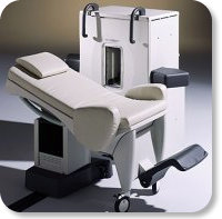
www.gemedicalsystems.com/rad/mri/products/artoscan/specs.html Developed by GE Lunar; the ARTOSCAN™-M is designed specifically for in-office musculoskeletal imaging. ARTOSCAN-M's compact, modular design allows placing within a clinical environment, bringing MRI to the patient. Patients remain outside the magnet at all times during the examinations, enabling constant patient-technologist contact. ARTOSCAN-M requires no special RF room, magnetic shielding, special power supply or air conditioning.
The C-SCAN™ (also known as Artoscan C) is developed from the ARTOSCAN™ - M, with a new computer platform.
Device Information and Specification
CLINICAL APPLICATION
Dedicated extremity
CONFIGURATION
Closed
Linear and dual phased array coil, knee, ankle, wrist coils
PULSE SEQUENCES
SE, GE, IR, STIR, FSE, 3D CE, GE-STIR, 3D GE, ME, TME, HSE
IMAGING MODES
Single, multislice, volume study, fast scan, multi slab, cine
TR
12 - 5,000 msec
TE
5 - 220 msec
SINGLE SLICE
0.8 sec/image
MULTISLICE
0.8 sec/image
FOV
10 - 20 cm
SLICE THICKNESS
2D: 2 mm - 10 mm;
3D: 0.6 mm - 10 mm
512 x 512
MEASURING MATRIX
256 x 256 maximum
PIXEL INTENSITY
4,096 gray lvls, 256 lvls in 3D
MAGNET TYPE
Ferrite Permanent
MAGNET WEIGHT
965 kg
POWER REQUIREMENTS
100/110/200/220/230/240V
STRENGTH
10 mT/m
5 GAUSS FRINGE FIELD, radial/axial
28 cm/60 cm
Passive
spacer

• View the DATABASE results for 'ARTOSCAN™ - M' (3).Open this link in a new window

Searchterm 'Phased Array Coil' was also found in the following services: 
spacer
Resources  (2)  Forum  (1)  
 
Array CoilInfoSheet: - Coils - 
Intro, 
Overview, 
etc.MRI Resource Directory:
 - Coils -
 
An array coil combines the advantages of smaller coils (high SNR) with those of larger coils (large measurement field). This type of RF coil is composed of separate multiple smaller coils, which can be used individually (switchable coil) or combined.
When used simultaneously, the elements can either be:
coupled array coils - electrically coupled to each other through common transmission lines or mutual inductance
isolated array coils - electrically isolated from each other with separate transmission lines and receivers and minimum effective mutual inductance, and with the signals from each transmission line processed independently or at different frequencies
phased array coils - multiple small coils arranged to efficiently cover a specific anatomic region and obtain high-resolution, high-SNR images of a larger volume. The data from the individual coils is integrated by special software to produce the high-resolution images.

See also the related poll result: '3rd party coils are better than the original manufacturer coils'
 
Images, Movies, Sliders:
 Anatomic Imaging of the Lumbar Spine  Open this link in a new window
      

Courtesy of  Robert R. Edelman

 
spacer

• View the DATABASE results for 'Array Coil' (22).Open this link in a new window


• View the NEWS results for 'Array Coil' (1).Open this link in a new window.
 
Further Reading:
  News & More:
3T MRI-Compatible Small Body Array Gets FDA Nod
Monday, 15 January 2024   by www.diagnosticimaging.com    
Endorectal Coil Improves Prostate Cancer Detection
Friday, 25 November 2005   by www.sciencedaily.com    
MRI Resources 
Used and Refurbished MRI Equipment - MRI Technician and Technologist Schools - Implant and Prosthesis pool - MRI Reimbursement - NMR - Homepages
 
Coil DiameterInfoSheet: - Coils - 
Intro, 
Overview, 
etc.
 
MRI coils with a small diameter obtain a higher signal to noise ratio (SNR) than coils with a large diameter. A surface coil with a small diameter can be used to improve the resolution because the area of interest is around the optimal signal depth. The field of view of a (superficial) surface coil is half the diameter of the coil. A disadvantage is a lower sensitive volume of the coil. By combining several coils with small diameters (phased array coil) to record the signal simultaneously and independently, the SNR level improves considerably.
spacer

• View the DATABASE results for 'Coil Diameter' (3).Open this link in a new window

MRI Resources 
Most Wanted - Brain MRI - IR - Safety Products - Liver Imaging - Developers
 
     1 - 5 (of 24)     next
Result Pages : [1]  [2]  [3 4 5]
 Random Page
 
Share This Page
FacebookTwitterLinkedIn

MR-TIP    
Community   
User
Pass
Forgot your UserID/Password ?    


New acceleration techniques will :
reduce scan times 
cause artifacts 
increase expenses 
be useful if you have a lot of experience 
doesn't do much 
never heard of 

Look
      Ups


MR-TIP.com uses cookies! By browsing MR-TIP.com, you agree to our use of cookies.

Magnetic Resonance - Technology Information Portal
Member of SoftWays' Medical Imaging Group - MR-TIP • Radiology-TIP • Medical-Ultrasound-Imaging • 
Copyright © 2003 - 2024 SoftWays. All rights reserved. [ 21 November 2024]
Terms of Use | Privacy Policy | Advertising
 [last update: 2024-02-26 03:41:00]