 | Info
Sheets |
| | | | | | | | | | | | | | | | | | | | | | | | |
 | Out-
side |
| | | | |
|
| | | | | |  | Searchterm 'sequence' was also found in the following services: | | | | |
|  |  |
| |
|
| |  | | | | | | | | |  Further Reading: Further Reading: | | Basics:
|
|
News & More:
| |
| |
|  | |  |  |  |
| |
|

(IR) The inversion recovery pulse sequence produces signals, which represent the longitudinal magnetization existing after the application of a 180° radio frequency pulse that rotates the magnetization Mz into the negative plane. After an inversion time (TI - time between the starting 180° pulse and the following 90° pulse), a further 90° RF pulse tilts some or all of the z-magnetization into the xy-plane, where the signal is usually rephased with a 180° pulse as in the spin echo sequence. During the initial time period, various tissues relax with their intrinsic T1 relaxation time.
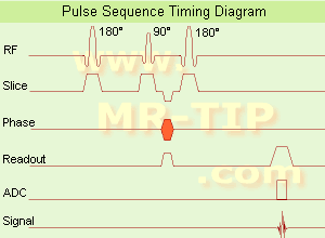
In the pulse sequence timing diagram, the basic inversion recovery sequence is illustrated. The 180° inversion pulse is attached prior to the 90° excitation pulse of a spin echo acquisition.
See also the Pulse Sequence Timing Diagram. There you will find a description of the components.
The inversion recovery sequence has the advantage, that it can provide very strong contrast between tissues having different T1 relaxation times or to suppress tissues like fluid or fat.
But the disadvantage is, that the additional inversion radio frequency RF pulse makes this sequence less time efficient than the other pulse sequences.
Contrast values:
PD weighted: TE: 10-20 ms, TR: 2000 ms, TI: 1800 ms
T1 weighted: TE: 10-20 ms, TR: 2000 ms, TI: 400-800 ms
T2 weighted: TE: 70 ms, TR: 2000 ms, TI: 400-800 ms
See also Inversion Recovery, Short T1 Inversion Recovery, Fluid Attenuation Inversion Recovery, and Acronyms for 'Inversion Recovery Sequence' from different manufacturers. | | | |  | |
• View the DATABASE results for 'Inversion Recovery Sequence' (8).
| | | | |  Further Reading: Further Reading: | Basics:
|
|
News & More:
| |
| |
|  | |  |  |  |
| |
|
| |  | |
• View the DATABASE results for 'Pulse Sequence Timing Diagram' (7).
| | | | |
|  |  | Searchterm 'sequence' was also found in the following services: | | | | |
|  |  |
| |
|
Spoiled gradient echo sequences use a spoiler gradient on the slice select axis during the end module to destroy any remaining transverse magnetization after the readout gradient, which is the case for short repetition times.
As a result, only z-magnetization remains during a subsequent excitation. This types of sequences use semi-random changes in the phase of radio frequency pulses to produce a spatially independent phase shift.
Companies use different acronyms to describe certain techniques.
Different terms for these gradient echo pulse sequences:
CE-FFE-T1 Contrast Enhanced Fast Field Echo with T1 Weighting,
GFE Gradient Field Echo,
FLASH Fast Low Angle Shot,
PS Partial Saturation,
RF spoiled FAST RF Spoiled Fourier Acquired Steady State Technique,
RSSARGE Radio Frequency Spoiled Steady State Acquisition Rewound Gradient Echo
S-GRE Spoiled Gradient Echo,
SHORT Short Repetition Techniques,
SPGR Spoiled Gradient Recalled (spoiled GRASS),
STAGE T1W T1 weighted Small Tip Angle Gradient Echo,
T1-FAST T1 weighted Fourier Acquired Steady State Technique,
T1-FFE T1 weighted Fast Field Echo.
In this context, 'contrast enhanced' refers to the pulse sequence, it does not mean enhancement with a contrast agent. | |  | |
• View the DATABASE results for 'Spoiled Gradient Echo Sequence' (11).
| | | | |  Further Reading: Further Reading: | News & More:
|
|
| |
|  | |  |  |  |
| |
|
| |  | |
• View the DATABASE results for 'Gradient Recalled Echo Sequence' (7).
| | | | |  Further Reading: Further Reading: | Basics:
|
|
| |
|  | |  |  |
|  | | |
|
| |
 | Look
Ups |
| |