Magnetic Resonance - Technology Information Portal Welcome to MRI Technology
Info
  Sheets

Out-
      side


 'Frequency' 
SEARCH FOR    
 
  2 3 5 A B C D E F G H I J K L M N O P Q R S T U V W X Y Z
Result : Searchterm 'Frequency' found in 23 terms [] and 195 definitions []
previous     81 - 85 (of 218)     next
Result Pages : [1 2 3 4 5]  [6 7 8 9 10 11 12 13 14 15 16 17 18 19 20 ... ]
Searchterm 'Frequency' was also found in the following services: 
spacer
News  (11)  Resources  (6)  Forum  (11)  
 
Nuclear Magnetic Resonance Signal
 
The electromagnetic signal in the radio-frequency range produced by the precession of the transverse magnetization of the spins. The rotation of the transverse magnetization induces a voltage in a receiving antenna (coil), which is amplified and demodulated by the receiver circuits. Electromagnetic signal in the radio frequency range produced by the precession of the transverse magnetization of the spins. The rotation of the transverse magnetization induces a voltage in a coil, which is amplified and demodulated by the receiver;; the signal may refer only to this induced voltage.
spacer
 
Further Reading:
  Basics:
Spin echoes, CPMG and T2 relaxation - Introductory NMR & MRI from Magritek
2013   by www.azom.com    
NMR Spectroscopy - Theory
   by www.shu.ac.uk    
  News & More:
A powder to enhance NMR signals
Thursday, 12 December 2013   by phys.org    
Searchterm 'Frequency' was also found in the following services: 
spacer
Radiology  (24) Open this link in a new windowUltrasound  (158) Open this link in a new window
Parallel Imaging TechniqueForum -
related threadsInfoSheet: - Sequences - 
Intro, 
Overview, 
Types of, 
etc.
 
In parallel MR imaging, a reduced data set in the phase encoding direction(s) of k-space is acquired to shorten acquisition time, combining the signal of several coil arrays. The spatial information related to the phased array coil elements is utilized for reducing the amount of conventional Fourier encoding.
First, low-resolution, fully Fourier-encoded reference images are required for sensitivity assessment. Parallel imaging reconstruction in the Cartesian case is efficiently performed by creating one aliased image for each array element using discrete Fourier transformation. The next step then is to create an full FOV image from the set of intermediate images. Parallel reconstruction techniques can be used to improve the image quality with increased signal to noise ratio, spatial resolution, reduced artifacts, and the temporal resolution in dynamic MRI scans.
Parallel imaging algorithms can be divided into 2 main groups:
Image reconstruction produced by each coil (reconstruction in the image domain, after Fourier transform): SENSE (Sensitivity Encoding), PILS (Partially Parallel Imaging with Localized Sensitivity), ASSET.
Reconstruction of the Fourier plane of images from the frequency signals of each coil (reconstruction in the frequency domain, before Fourier transform): GRAPPA.
Additional techniques include SMASH, SPEEDER™, IPAT (Integrated Parallel Acquisition Techniques - derived of GRAPPA a k-space based technique) and mSENSE (an image based enhanced version of SENSE).
 
Images, Movies, Sliders:
 Circle of Willis, Time of Flight, MIP  Open this link in a new window
    
SlidersSliders Overview

 
spacer

• View the DATABASE results for 'Parallel Imaging Technique' (12).Open this link in a new window

 
Further Reading:
  Basics:
Parallel MRI Using Multiple Receiver Coils
   by www-math.mit.edu    
Coil Arrays for Parallel MRI: Introduction and Overview.
   by www.mr.ethz.ch    
  News & More:
Cardiac MRI Becoming More Widely Available Thanks to AI and Reduced Exam Times
Wednesday, 19 February 2020   by www.dicardiology.com    
The Effects of Breathing Motion on DCE-MRI Images: Phantom Studies Simulating Respiratory Motion to Compare CAIPIRINHA-VIBE, Radial-VIBE, and Conventional VIBE
Tuesday, 7 February 2017   by www.kjronline.org    
Implementation of Dual-Source RF Excitation in 3 T MR-Scanners Allows for Nearly Identical ADC Values Compared to 1.5 T MR Scanners in the Abdomen
Wednesday, 29 February 2012   by www.plosone.org    
Clinical evaluation of a speed optimized T2 weighted fast spin echo sequence at 3.0 T using variable flip angle refocusing, half-Fourier acquisition and parallel imaging
Wednesday, 25 October 2006
MRI Resources 
MRI Technician and Technologist Schools - Equipment - Homepages - Spine MRI - Universities - Abdominal Imaging
 
Phase Wrapping ArtifactInfoSheet: - Artifacts - 
Case Studies, 
Reduction Index, 
etc.MRI Resource Directory:
 - Artifacts -
 
Parts of the body, which extend beyond the Field of view in the phase encoding direction may still be visible in the image as artifacts.
Please note that aliasing in the frequency direction is also possible but can be eliminated in the same manner or by applying frequency specific filters to the received signal.

See Aliasing Artifact.
spacer

• View the DATABASE results for 'Phase Wrapping Artifact' (2).Open this link in a new window

 
Further Reading:
  Basics:
Aliasing or wrap around artifacts
Thursday, 31 March 2011   by de.slideshare.net    
Searchterm 'Frequency' was also found in the following services: 
spacer
News  (11)  Resources  (6)  Forum  (11)  
 
Pulse Sequence Timing DiagramInfoSheet: - Sequences - 
Intro, 
Overview, 
Types of, 
etc.
 
Spin Echo Timing Diagram 
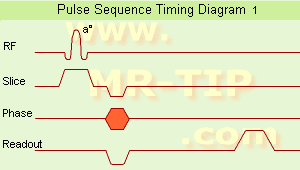
The schematic figures of a
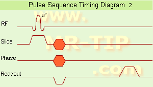
 pulse sequence timing diagram illustrate the steps of basic hardware activity that are incorporated into a pulse sequence. Time during sequence execution is indicated along the horizontal axes. Each line belongs to a different hardware component. One line is needed for the radio frequency transmitter and also one for each gradient (Gs = slice selection gradient x, Gf = phase encoding gradient y, Gf = frequency encoding gradient z, also called readout gradient).
In picture 1, a timing diagram for a 2D pulse sequence is shown.
Slice selection and signal detection are repeated in duration, relative timing and amplitude, each time the sequence is repeated. A single phase encoding component is present each time the sequence is executed.
Additional lines are added for ADC (Analog to Digital Converter) and sampling. A gradient pulse is shown as a deviation above or below the horizontal line. Simultaneous component activities such as the RF pulse and slice selection gradient are indicated as a non-zero deviation from both lines at the same horizontal position. Simple deviations from zero show constant amplitude gradient pulse. Gradient amplitudes that change during the measurement, e.g. phase encoding are represented as hatched regions.

Spin Echo Timing Diagram The second picture shows a timing diagram for a 3D pulse sequence.
Volume excitation and signal detection are repeated in duration, relative timing and amplitude, each time the sequence is repeated. Two phase encoding components are present, one in the phase encoding direction and the other in slice selection direction (irrespectively incremented in amplitude) in each time the sequence is executed. A description of the comparison of hardware activity between different pulse sequences.
spacer

• View the DATABASE results for 'Pulse Sequence Timing Diagram' (7).Open this link in a new window

Searchterm 'Frequency' was also found in the following services: 
spacer
Radiology  (24) Open this link in a new windowUltrasound  (158) Open this link in a new window
Readout Gradient
 
Magnetic field gradient applied during the period when the receiver components are on. The application of this gradient, which is active during the period when the echo is being formed, results in the frequency encoding of the object being imaged.
Also called frequency encoding gradient.
spacer

• View the DATABASE results for 'Readout Gradient' (9).Open this link in a new window

 
Further Reading:
  News & More:
Evaluation of Absorbed Dose by MRI Read-Out
Saturday, 18 November 2017   by www.jstage.jst.go.jp    
MRI Resources 
Pediatric and Fetal MRI - Musculoskeletal and Joint MRI - Coils - Supplies - Shoulder MRI - Health
 
previous      81 - 85 (of 218)     next
Result Pages : [1 2 3 4 5]  [6 7 8 9 10 11 12 13 14 15 16 17 18 19 20 ... ]
 Random Page
 
Share This Page
FacebookTwitterLinkedIn

MR-TIP    
Community   
User
Pass
Forgot your UserID/Password ?    


New acceleration techniques will :
reduce scan times 
cause artifacts 
increase expenses 
be useful if you have a lot of experience 
doesn't do much 
never heard of 

Look
      Ups


MR-TIP.com uses cookies! By browsing MR-TIP.com, you agree to our use of cookies.

Magnetic Resonance - Technology Information Portal
Member of SoftWays' Medical Imaging Group - MR-TIP • Radiology-TIP • Medical-Ultrasound-Imaging • 
Copyright © 2003 - 2024 SoftWays. All rights reserved. [ 2 May 2024]
Terms of Use | Privacy Policy | Advertising
 [last update: 2024-02-26 03:41:00]