| Info
Sheets |
| | | | | | | | | | | | | | | | | | | | | | | | |
 | Out-
side |
| | | | |
|
| | | | | |  | Searchterm 'Phase' was also found in the following services: | | | | |
|  |  |
| |
|
Respiratory compensation reduces motion artifacts due to breathing. The approach is to reassign the echoes that are sensitive to respiratory motion in the central region of k-space. The outer lines of phase encoding normally contain the echoes where the motion from expiration is the greatest. The central portion of k-space will have encoded the echoes where inspiration and expiration are minimal. By a bellows device fixed to the abdomen, monitoring of the diaphragm excursion is possible. Respiratory compensation does not increase scan time with most systems.
An advantage of very fast sequences is the possibility of breath holding during the acquisition to eliminate motion artifacts.
Breath hold is commonly used on most abdominal studies where images are acquired using gradient echo-based sequences during a brief inspiratory period (20-30 seconds). To enhance the breath holding endurance of the patient, connecting the patient to oxygen at a 1-liter flow rate via a nasal cannula has been shown to be helpful.
Also called PEAR, Respiratory Trigger, Respiratory Gating, PRIZE, FREEZE, Phase Reordering.
See also Phase Encoding Artifact Reduction, Respiratory Ordered Phase Encoding. | | | | | |  Further Reading: Further Reading: | News & More:
|
|
| |
| | | Searchterm 'Phase' was also found in the following services: | | | | |
| | |
| |
|
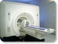
(Signa VH/i 3.0T)
With GE Healthcare
leading-edge technology in ultra-high-field imaging. The 3 T VH/i provides a platform for advanced applications in radiology, cardiology, psychology and psychiatry. Real-time image processing lets you acquire multislice whole brain images and map brain functions for research or surgical planning. And the 3 T Signa VH/i is flexible enough to provide clinicians with high performance they require. It can provide not only outstanding features in brain scanning and neuro-system research, but also a wide range of use in scanning breasts, extremities, the spine and the cardiovascular systems.
Device Information and Specification CLINICAL APPLICATION Whole body
T/R quadrature head, T/R quadrature body, T/R phased array extremity (opt) SE, IR, 2D/3D GRE, FGRE, RF-spoiled GRE, FSE, Angiography: 2D/3D TOF, 2D/3D phase contrast vascular IMAGING MODES Single, multislice, volume study, fast scan, multi slab, cine, localizer 100 Images/sec with Reflex100 MULTISLICE 100 Images/sec with Reflex100 2D 0.5-100mm in 0.1mm incremental 128x512 steps 32 phase encode H*W*D 260cm x 238cm x 265cm POWER REQUIREMENTS 480 or 380/415, 3 phase ||
COOLING SYSTEM TYPE Closed-loop water-cooled grad. Less than 0.14 L/hr liquid He | | | |
• View the DATABASE results for 'Signa 3.0T™' (2).
| | | | |
| | | | | |
| |
|
A technique, which produces a 3 dimensional image of an object. The advantage of this approach is that the signal, acquired from the entire volume has an increased SNR. 'Slices' are defined by a second phase encoded axis, which divides the volume into 'partitions'.
There is no gap between the slices in 3D volume imaging, therefore thin slices are possible. The Gz phase encoding gradient is set for several slices in one. But 3D takes more time with thin slices because of this phase encoding gradient. With conventional thin slice imaging, the SNR is poor, with 3D volume imaging this is not the case because the slab (volume) is responsible for SNR. | | | | | |
• View the DATABASE results for '3 Dimensional Imaging' (5).
| | |
• View the NEWS results for '3 Dimensional Imaging' (1).
| | | | | | Further Reading: | | Basics:
|
|
News & More:
| |
| |
| | | Searchterm 'Phase' was also found in the following services: | | | | |
| | |
| |
|
If the receiving RF coil is sensitive to tissue signal arising from outside the desired FOV, this undesired signal may be incorrectly mapped to a location within the image, a phenomenon known as aliasing. This is a consequence of the acquired k-space frequencies not being sampled densely enough, whereby portions of the object outside of the desired FOV get mapped to an incorrect location inside the FOV.
The sampling frequency should be at least twice the frequency being sampled. The maximum measurable frequency is therefore equal to half the sampling frequency. This is the so-called Nyquist limit. When the frequency is higher than the Nyquist limit, aliasing occurs.
A similar problem occurs in the phase encoding direction, where the phases of signal-bearing tissues outside of the FOV in the y-direction are a replication of the phases that are encoded within the FOV. This signal will be mapped, or wrapped back into the image at incorrect locations, and is seen as artifact.
See also Aliasing Artifact. | | | |
• View the DATABASE results for 'Aliasing' (19).
| | | | | | Further Reading: | News & More:
|
|
| |
| | | Searchterm 'Phase' was also found in the following services: | | | | |
| | |
| |
|
A bolus is a rapid infusion of high dose contrast agent. Dynamic and accumulation phase imaging can be performed after bolus injection. Since the transit time of the bolus through the tissue is only a few seconds, high temporal resolution imaging can be required to obtain sequential images during the wash in and wash out of the contrast material and, therefore, resolve the first pass of the tracer.
For the same injected dose of contrast agent the injection rate (and, consequently, the total injected volume) modifies the bolus peak profile. Increasing the injection rate produces a sharpening of the peak
(Cmax increase, Tmax decrease, peak length decrease). At a
low injection rate, the first pass presents a plateau form.
Substantial changes in the gadolinium concentrations during signal acquisition induce artifacts. Furthermore, the haemodynamic
parameters ( cardiac output, blood pressure) influence
the bolus profile.
The characteristics of gadolinium agents are favorable in the early bolus
phase, whereas the advantages of large complexes (e.g. blood pool agents) and ultrasmall superparamagnetic iron oxide ( USPIO) are most evident in the distribution phase. | | | | | |
• View the DATABASE results for 'Bolus Injection' (9).
| | | | | | Further Reading: | News & More:
|
|
| |
| | | | |
| | | |
|
| |
 | Look
Ups |
| |