| Info
Sheets |
| | | | | | | | | | | | | | | | | | | | | | | | |
 | Out-
side |
| | | | |
|
| | | | | |  | Searchterm 'Phase' was also found in the following services: | | | | |
|  |  |
| |
|
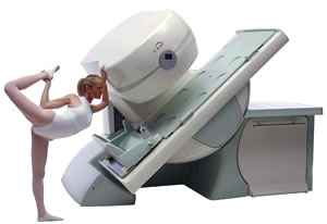
From Esaote S.p.A.;
Esaote introduced the new G-SCAN at the RSNA in Dec. 2004. The G-SCAN covers almost all musculoskeletal applications including the spine. The tilting gantry is designed for scanning in weight-bearing positions. This unique MRI scanner is developed in line with the Esaote philosophy of creating high quality MRI systems that are easy to install and that have a low breakeven point.
Device Information and Specification
SE, GE, IR, STIR, TSE, 3D CE, GE-STIR, 3D GE, ME, TME, HSE
100 up to 350 mm, 25 mm displayed
POWER REQUIREMENTS
100/110/200/220/230/240 V
| | | | | |
| | | Searchterm 'Phase' was also found in the following services: | | | | |
| | |
| |
|
Quick Overview
REASON
Motion, heartbeat, respiration
HELP
Triggering, breath hold, pharmaceuticals to reduce bowel motion
Ghosting artifacts are in the most cases caused by movements (e.g., respiratory motion, bowel motion, arterial pulsations, swallowing, and heartbeat) and appear in the phase encoding direction.

Image Guidance
| | | |
• View the DATABASE results for 'Ghosting Artifact' (5).
| | | | |  Further Reading: Further Reading: | Basics:
|
|
| |
| | | | | |
| |
|
| | | |
• View the DATABASE results for 'Gradient Motion Rephasing' (2).
| | | | | | Further Reading: | Basics:
|
|
| |
| | | Searchterm 'Phase' was also found in the following services: | | | | |
| | |
| |
|
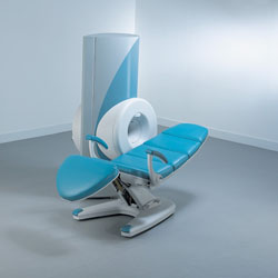
From ONI Medical Systems, Inc.;
MSK-Extreme™ MRI system is a dedicated high field extremity imaging device, designed to provide orthopedic surgeons and other physicians with detailed diagnostic images of the foot, ankle, knee, hand, wrist and elbow, all with the clinical confidence and advantages derived from high field, whole body MRI units. The light weight (less than 650 kg) of the OrthOne System performs rapid patient studies, is easy to operate, has a patient friendly open environment and can be installed in a practice office or hospital, all at a cost similar to a low field extremity machine.
New features include a more powerful operating system that offers increased scan speed as well as a 160-mm knee coil with higher signal to noise ratio, and the option of a CD burner.
Device Information and Specification 16 cm knee, 18 cm lower extremity;; 12.3 cm upper extremity, additional high resolution v-SPEC Coils: 80 mm, 100 mm, or 145 mm. SE, FSE, GE2D, GE3D, Inversion recovery (IR), Driven Equilibrium, Fat Saturation (FS), STIR, MT, PD, Flow Compensation (FC), RF spoiling, MTE, No Phase Wrap (NPW) IMAGING MODES Scout, single, multislice, volume 2D less than 200 msec/image X/Y: 64-512; 2 pixel steps 4,096 grey lvls; 256 lvls in 3D POWER REQUIREMENTS 115VAC, 1 phase, 20A; 208VAC, 3 phase, 30A COOLING SYSTEM TYPE LHe with 2 stage cold head 1.25m radial x 1.8m axial | | | | | | | Further Reading: | Basics:
|
|
| |
| | | Searchterm 'Phase' was also found in the following services: | | | | |
| | |
| |
|
Quick Overview Please note that there are different common names for this artifact.
DESCRIPTION
Striped ghosts with a shift of half the field of view
Machine imperfection-based artifacts manifest themselves due to the fact that the odd k-space lines are acquired in a different direction than the even k-space lines. Slight differences in timing result in shifts of the echo in the acquisition window. By the shift theorem, such shifts in the time domain data then produce linear phase differences in the frequency domain data.
Without correction, such phase differences in every second line produce striped ghosts with a shift of half the field of view, so-called Nyquist ghosts. Shifts in the applied magnetic field can also produce similar (but constant in amplitude) ghosts.
This artifact is commonly seen in an EPI image and can arise from both, hardware and sample imperfections.
A further source of machine-based artifact arises from the need to acquire the signal as quickly as possible. For this reason the EPI signal is often acquired during times when the gradients are being switched. Such sampling effectively means that the k-space sampling is not uniform, resulting in ringing artifacts in the image.
Image Guidance
Such artifacts can be minimized by careful setup of the spectrometer and/or correction of the data. For this reasons reference data are often collected, either as a separate scan or embedded in the imaging data.
The non-uniform sampling can be removed by knowing the form of the gradient switching. It is possible to regrid the data onto a uniform k-space grid. | | | |
• View the DATABASE results for 'Machine Imperfection Artifact' (2).
| | | | | | Further Reading: | Basics:
|
|
| |
| | | | |
| | |
| | | |
|
| |
 | Look
Ups |
| |