| Info
Sheets |
| | | | | | | | | | | | | | | | | | | | | | | | |
 | Out-
side |
| | | | |
|
| | | | | |  | Searchterm 'Signa' was also found in the following services: | | | | |
|  |  |
| |
|
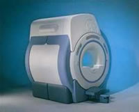
From GE Healthcare;
a friendly and less confining appearance targets the 7% of individuals who refuse to have an MRI because of claustrophobia. This open MRI system is also up to three times faster than other scanners, therefore the Signa OpenSpeed™ reducing exam time and scheduling
issues. In addition, a swing table provides better access and supports up to 500 pounds.
Device Information and Specification CLINICAL APPLICATION Whole body Standard: SE, IR, 2D/3D GRE and SPGR, Angiography: 2D/3D TOF, 2D/3D Phase Contrast;; 2D/3D FSE, 2D/3D FGRE and FSPGR, SSFP, FLAIR, EPI, optional: 2D/3D Fiesta, FGRET, Spiral, TensorTR 1.3 to 12000 msec in increments of 1 msec TE 0.4 to 2000 msec in increments of 1 msec 2D: 0.8mm - 20mm 3D: 0.1mm - 20mm 0.08 mm; 0.02 mm optional POWER REQUIREMENTS 200 - 480, 3-phase | | | | | |  Further Reading: Further Reading: | News & More:
|
|
| |
| | | | | |
| |
|
The elimination or reduction of a particular signal by, for example, the application of a narrow band frequency-selective preparation pulse centered at the resonant frequency of the signal. This can also be accomplished using an inversion recovery technique to null the signal as it recovers its longitudinal magnetization. | | | | | |
• View the DATABASE results for 'Signal Suppression' (2).
| | | | |
| | | | | |
| |
|
Quick Overview
DESCRIPTION
Line across the center of the image
REASON
Combination of problems

Image Guidance
If the problem persists, it must be addressed by a service representative. | | | |
• View the DATABASE results for 'FID Signal Artifact' (2).
| | | | | | Further Reading: | News & More:
|
|
| |
| | | Searchterm 'Signa' was also found in the following services: | | | | |
| | |
| |
|
( SNR or S/N) The signal to noise ratio is used in MRI to describe the relative contributions to a detected signal of the true signal and random superimposed signals ('background noise') - a criterion for image quality.
One common method to increase the SNR is to average several measurements of the signal, on the expectation that random contributions will tend to cancel out. The SNR can also be improved by sampling larger volumes (increasing the field of view and slice thickness with a corresponding loss of spatial resolution) or, within limits, by increasing the strength of the magnetic field used. Surface coils can also be used to improve local signal intensity. The SNR will depend, in part, on the electrical properties of the sample or patient being studied.
The SNR increases in proportion to voxel volume (1/resolution), the square root of the number of acquisitions ( NEX), and the square root of the number of scans ( phase encodings). SNR decreases with the field of view squared (FOV2) and wider bandwidths. See also Signal Intensity and Spin Density.
Measuring SNR:
Record the mean value of a small ROI placed in the most homogeneous area of tissue with high signal intensity (e.g. white matter in thalamus). Calculate the standard deviation for the largest possible ROI placed outside the object in the image background (avoid ghosting/aliasing or eye movement artifact regions).
The SNR is then:
Mean Signal/Standard Deviation of Background Noise | | | | | |
• View the DATABASE results for 'Signal to Noise Ratio' (48).
| | |
• View the NEWS results for 'Signal to Noise Ratio' (2).
| | | | | | Further Reading: | | Basics:
|
|
News & More:
| |
| |
| | | | | |
| |
|
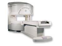
Device Information and Specification CLINICAL APPLICATION Whole body Head and body coil standard; all other coils optional; open architecture makes system compatible with a wide selection of coils Standard: SE, IR, 2D/3D GRE and SPGR, Angiography;; 2D/3D TOF, 2D/3D Phase Contrast;; 2D/3D FSE, 2D/3D FGRE and FSPGR, SSFP, FLAIR, optional: EPI, 2D/3D Fiesta, FGRET, SpiralTR 4.4 msec to 12000 msec in increments of 1 msec TE 1.0 to 2000 msec; increments of 1 msec Simultaneous scan and reconstruction;; up to 100 images/second with Reflex 100 2D 0.7 mm to 20 mm; 3D 0.1 mm to 5 mm 128x512 steps 32 phase encode 0.08 mm; 0.02 mm optional POWER REQUIREMENTS 480 or 380/415 V Less than 0.03 L/hr liquid heliumSTRENGTH SmartSpeed 23 mT/m, HiSpeed Plus 33 mT/m 4.0 m x 2.8 m axial x radial | | | |
• View the DATABASE results for 'Signa Infinity 1.0T™' (2).
| | | | |
| | | | |
| | |
| | | |
|
| |
 | Look
Ups |
| |