| Info
Sheets |
| | | | | | | | | | | | | | | | | | | | | | | | |
 | Out-
side |
| | | | |
|
| | | | | |  | Searchterm 'pulse sequences' was also found in the following services: | | | | |
|  |  |
| |
|
Quick Overview Please note that there are different common names for this artifact.
DESCRIPTION
Black or bright band
During frequency encoding, fat protons precess slower than water protons in the same slice because of their magnetic shielding. Through the difference in resonance frequency between water and fat, protons at the same location are misregistrated (dislocated) by the Fourier transformation, when converting MRI signals from frequency to spatial domain. This chemical shift misregistration cause accentuation of any fat-water interfaces along the frequency axis and may be mistaken for pathology. Where fat and water are in the same location, this artifact can be seen as a bright or dark band at the edge of the anatomy.
Protons in fat and water molecules are separated by a chemical shift of about 3.5 ppm. The actual shift in Hertz (Hz) depends on the magnetic field strength of the magnet being used. Higher field strength increases the misregistration, while in contrast a higher gradient strength has a positive effect. For a 0.3 T system operating at 12.8 MHz the shift will be 44.8 Hz compared with a 223.6 Hz shift for a 1.5 T system operating at 63.9 MHz.

Image Guidance
| | | | | | | | | | |  Further Reading: Further Reading: | | Basics:
|
|
News & More:
| |
| |
| | | | | |
| |
|
Contrast is the relative difference of signal intensities in two adjacent regions of an image.
Due to the T1 and T2 relaxation properties in magnetic resonance imaging, differentiation between various tissues in the body is possible. Tissue contrast is affected by not only the T1 and T2 values of specific tissues, but also the differences in the magnetic field strength, temperature changes, and many other factors. Good tissue contrast relies on optimal selection of appropriate pulse sequences ( spin echo, inversion recovery, gradient echo, turbo sequences and slice profile).
Important pulse sequence parameters are TR ( repetition time), TE (time to echo or echo time), TI (time for inversion or inversion time) and flip angle. They are associated with such parameters as proton density and T1 or T2 relaxation times. The values of these parameters are influenced differently by different tissues and by healthy and diseased sections of the same tissue.
For the T1 weighting it is important to select a correct TR or TI. T2 weighted images depend on a correct choice of the TE. Tissues vary in their T1 and T2 times, which are manipulated in MRI by selection of TR, TI, and TE, respectively. Flip angles mainly affect the strength of the signal measured, but also affect the TR/TI/TE parameters.
Conditions necessary to produce different weighted images:
T1 Weighted Image: TR value equal or less than the tissue specific T1 time - TE value less than the tissue specific T2 time.
T2 Weighted Image: TR value much greater than the tissue specific T1 time - TE value greater or equal than the tissue specific T2 time.
Proton Density Weighted Image: TR value much greater than the tissue specific T1 time - TE value less than the tissue specific T2 time.
See also Image Contrast Characteristics, Contrast Reversal, Contrast Resolution, and Contrast to Noise Ratio. | | | | | |
• View the DATABASE results for 'Contrast' (373).
| | |
• View the NEWS results for 'Contrast' (77).
| | | | | | Further Reading: | | Basics:
|
|
News & More:
| |
| |
| | | | | |
| |
|
Contrast enhanced GRE sequences provide T2 contrast but have a relatively poor SNR. Repetitive RF pulses with small flip angles together with appropriate gradient profiles lead to the superposition of two resonance signals.
The first signal is due to the free induction decay FID observed after the first and all ensuing RF excitations.
The second is a resonance signal obtained as a result of a spin echo generated by the second and all addicted RF-pulses.
Hence it is absent after the first excitation, it is a result of the free induction decay of the second to last RF-excitation and has a TE, which is almost 2TR.
For this echo to occur the gradients have to be completely symmetrical relative to the half time between two RF-pulses, a condition that makes it difficult to integrate this pulse sequence into a multiple slice imaging technique.
The second signal not only contains echo contributions from free induction decay, but obviously weakened by T2-decay.
Since the echo is generated by a RF-pulse, it is truly T2 rather than T2* weighted. Correspondingly it is also less sensitive to susceptibility changes and field inhomogeneities.
Companies use different acronyms to describe certain techniques.
Different terms (see also acronyms) for these gradient echo pulse sequences:
CE-FAST Contrast Enhanced Fourier Acquired Steady State,
CE-FFE Contrast Enhanced Fast Field Echo,
CE-GRE Contrast Enhanced Gradient-Echo,
DE-FGR Driven Equilibrium FGR,
FADE FASE Acquisition Double Echo,
PSIF Reverse Fast Imaging with Steady State Precession,
SSFP Steady State Free Precession,
T2 FFE Contrast Enhanced Fast Field Echo (T2 weighted).
In this context, 'contrast enhanced' refers to the pulse sequence, it does not mean enhancement with a contrast agent. | | | |
• View the DATABASE results for 'Contrast Enhanced Gradient Echo Sequence' (4).
| | | | |
| | | Searchterm 'pulse sequences' was also found in the following services: | | | | |
| | |
| |
|
(CE MRA) Contrast enhanced MR angiography is based on the T1 values of blood, the surrounding tissue, and paramagnetic contrast agent.
T1-shortening contrast agents reduces the T1 value of the blood (approximately to 50 msec, shorter than that of the surrounding tissues) and allow the visualization of blood vessels, as the images are no longer dependent primarily on the inflow effect of the blood.
Contrast enhanced MRA is performed with a short TR to have low signal (due to the longer T1) from the stationary tissue, short scan time to facilitate breath hold imaging, short TE to minimize T2* effects and a bolus injection of a sufficient dose of a gadolinium chelate.
Images of the region of interest are performed with 3D spoiled gradient echo pulse sequences. The enhancement is maximized by timing the contrast agent injection such that the period of maximum arterial concentration corresponds to the k-space acquisition. Different techniques are used to ensure optimal contrast of the arteries e.g., bolus timing, automatic bolus detection, bolus tracking, care bolus.
A high resolution with near isotropic voxels and minimal pulsatility and misregistration artifacts should be striven for. The postprocessing with the maximum intensity projection ( MIP) enables different views of the 3D data set.
Unlike conventional MRA techniques based on velocity dependent inflow or phase shift techniques, contrast enhanced MRA exploits the
gadolinium induced T1-shortening effects. CE MRA reduces or eliminates most of the artifacts of time of flight angiography or phase contrast angiography. Advantages are the possibility of in plane imaging of the blood vessels, which allows to examine large parts in a short time and high resolution scans in one breath hold.
CE MRA has found a wide acceptance in the clinical routine, caused by the
advantages:
•
3D MRA can be acquired in any plane, which means that
greater vessel coverage can be obtained at high
resolution with fewer slices (aorta, peripheral vessels);
•
the possibility to perform a time resolved examination
(similarly to conventional angiography);
•
no use of ionizing radiation; paramagnetic agents have a beneficial safety.
| | | | | |
• View the DATABASE results for 'Contrast Enhanced Magnetic Resonance Angiography' (14).
| | |
• View the NEWS results for 'Contrast Enhanced Magnetic Resonance Angiography' (2).
| | | | | | Further Reading: | Basics:
|
|
News & More:
| |
| |
| | | | | |
| |
|
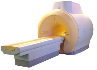
'MRI system is not an expensive equipment anymore.
ENCORE developed by ISOL Technology is a low cost MRI system with the advantages like of the 1.0T MRI scanner. Developed specially for the overseas market, the ENCORE is gaining popularity in the domestic market by medium sized hospitals.
Due to the optimum RF and Gradient application technology. ENCORE enables to obtain high resolution imaging and 2D/3D Angio images which was only possible in high field MR systems.'
- Less consumption of the helium gas due to the ultra-lightweight magnet specially designed and manufactured for ISOL.
- Cost efficiency MR system due to air cooling type (equivalent to permanent magnetic).
- Patient processing speed of less than 20 minutes.'
Device Information and Specification
CLINICAL APPLICATION
Whole body
CONFIGURATION
Short bore compact
| | | |
• View the DATABASE results for 'ENCORE 0.5T™' (2).
| | | | |
| | | | |
| | | |
|
| |
 | Look
Ups |
| |